


Chapter 4: Examples
4-6 802.1Q VLAN User’s Guide
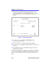
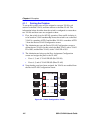
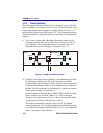
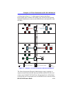
Switch 4
Switch 4 is set as follows:
1. Two VLANs are added to the list of VLANs in the Device/VLAN
Configuration screen and assigned to a FID. In this example they are
as follows:
• VLAN ID 2, FID 2, with a VLAN Name of Red
• VLAN ID 3, FID 3, with a VLAN Name of Blue
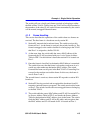
Because the VLANs are assigned to two separate FIDs, the users on
VLAN ID 2 and VLAN ID 3 cannot communicate with each other.
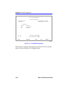
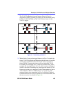
2. Ports 1 and 3 are assigned to the Port VLAN ID (PVID) as follows
using the Port Assignment Configuration screen:
• Port 1, VLAN ID: 2 for the Red VLAN
• Port 3, VLAN ID: 3 for the Blue VLAN
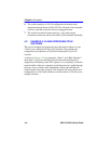
This causes the switch to classify all untagged frames received as
belonging to the VLAN specified by each port PVID and to replace the
previous PVID information in the port VLAN List with the new PVID
information. This makes Port 1 part of the Red VLAN, Port 3 part of
the Blue VLAN, and both are set as VLAN frame format of untagged.
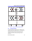
3. Port 4 is configured as a 1Q Trunk port as follows using the Port
Assignment Configuration screen:
• Port Mode: 1Q Trunk
Port 4 is set as an 802.1Q Trunk port, which makes the port eligible to
transmit to all VLANs, and all frames forwarded out this port are
forwarded as tagged frames. By default there is no PVID associated
with the trunk port and the port remains as a member of the Default
VLAN. With the original classification information inserted in the
frame Tag Header, the receiving switch will maintain the original
frame classification.