


Chapter 4: Examples
4-20 802.1Q VLAN User’s Guide
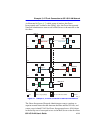
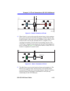
Switch 5
Switch 5 is set as follows:
1. Two VLANs are added to the list of VLANs in the Device/VLAN
Configuration screen. In this example, it is set as follows:
• VLAN ID 5, FID 5, with a VLAN Name of Yellow
• VLAN ID 6, FID 6, with a VLAN Name of Grey
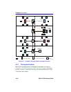
2. The Forward Default VLAN Out All Ports is set to YES using the
Device/VLAN Configuration screen. This adds the Default VLAN to
the Port VLAN List of every switch port.
3. To allow all frames (except the AppleTalk frames, which will be
prevented in steps 4 and 5) from being transmitted out Port 1 to Switch
3 and the network backbone, Port VLAN IDs are assigned to all switch
ports using the Port Assignment screen, as follows:
• Port 1, VLAN ID: 5 for the Yellow VLAN
• Port 2, VLAN ID: 5 for the Yellow VLAN
• Port 3, VLAN ID: 5 for the Yellow VLAN
• Port 4, VLAN ID: 5 for the Yellow VLAN
• Port 5, VLAN ID: 5 for the Yellow VLAN
• Port 6, VLAN ID: 5 for the Yellow VLAN
• Port 7, VLAN ID: 5 for the Yellow VLAN
• Port 8, VLAN ID: 5 for the Yellow VLAN
4. On the Protocol VLAN Configuration screen, the VLAN ID 6 of the
Grey VLAN is assigned to the AppleTalk protocol.
• VLAN ID 6, Protocol Type: AppleTalk, Status: ADD
This creates the protocol VLAN ID 6 that will handle only AppleTalk
frames and enables ports to be assigned the this VLAN.