


Chapter 4: Examples
4-2 802.1Q VLAN User’s Guide
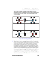
4.1.1 Solving the Problem
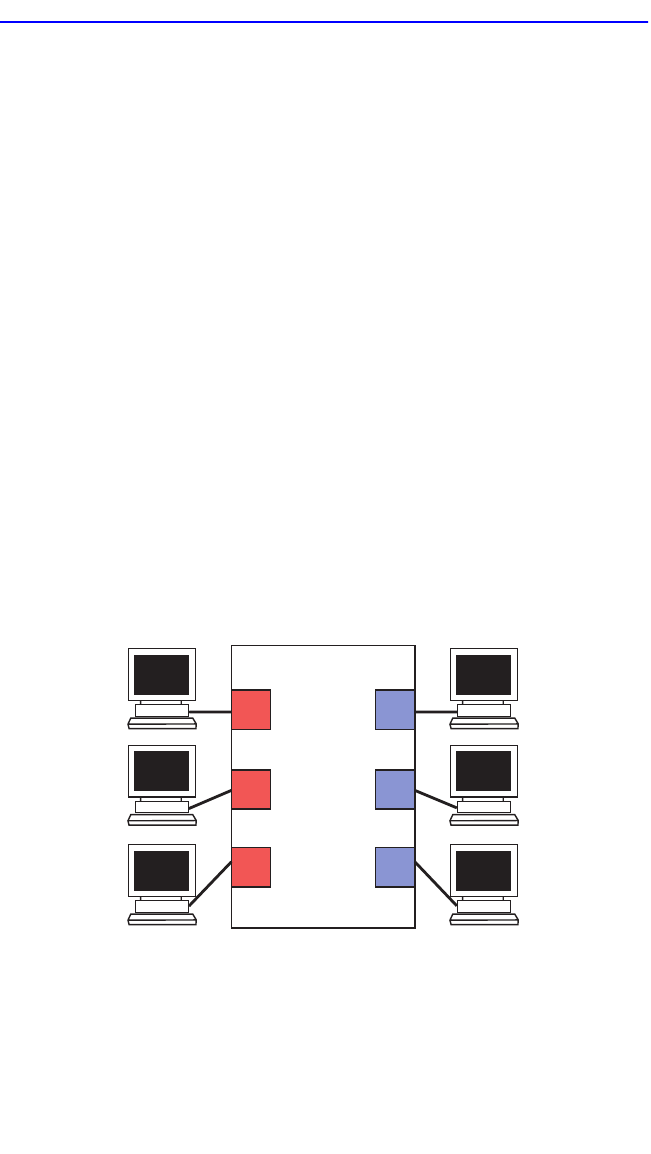
To set up this switch, users will be assigned to two new VLANs, red
stations to the Red VLAN, and blue stations to the Blue VLAN. The
information below describes how the switch is configured to create these
two VLANs and how users are assigned to them.
1. First, the switch is set for 802.1Q operation. Since traffic isolation is
to be based on VLAN membership alone, the switch is set so the Red
VLAN is a member of FID 2 and the Blue VLAN is a member of FID
3 from the Device/VLAN Configuration screen.
2. The Administrator uses the Device/VLAN Configuration screen to
define the two VLANs for this switch; the Red VLAN, with a VLAN
ID of 002, and the Blue VLAN, with a VLAN ID of 003.
3. The Administrator brings up the Port Assignment Configuration
screen and assigns the ports to the VLANs.
• Ports 1, 2, and 3: VLAN ID 002 (Red VLAN)
• Ports 4, 5, and 6: VLAN ID 003 (Blue VLAN)
4. Now that the ports have been assigned, the VLANs are enabled from
the Device/VLAN Configuration screen.
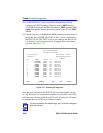
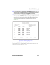
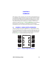
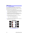
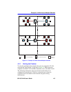
Figure 4-2 Switch Configured for VLANs
3 6
2
4
5
B2
B1
B3R1
R2
R2
802.1Q Switch
VLAN ID 002
VLAN ID 003VLAN ID 002
VLAN ID 003VLAN ID 002
VLAN ID 003
1
2263_12