


Example 4, Isolating Network Traffic According to Protocol
802.1Q VLAN User’s Guide 4-19
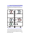
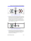
Switch 5 will be configured to isolate all AppleTalk protocol frame traffic
to the devices in the Grey VLAN and all other protocol traffic to the
Yellow VLAN. Switch 3 will link the traffic from Switch 5 to the
buildings network backbone.
Two 1Q Trunk ports must be activated and configured on Switch 3, and
one 1Q Trunk port must be activated and configured on Switch 4.
Ports 2, 3, 4, 5, 6, 7, and 8 of Switch 5 are connected to the Publication
Department devices. These ports will be configured to classify all
AppleTalk frames into the AppleTalk VLAN (Grey). The same ports will
also be configured to classify all other protocol frames into a second
VLAN (Yellow). Port 1 will be assigned to the Yellow VLAN to handle
the traffic between Switch 3 and 5.
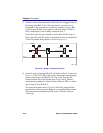
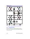
Switch 3
Switch 3 is set as follows:
1. One VLAN is added to the list of VLANs in the Device/VLAN
Configuration screen. In this example, Switch 3 is set as follows:
• VLAN ID 5, FID 5, with a VLAN Name of Yellow
2. The Forward Default VLAN Out All Ports is set to YES using the
Device/VLAN Configuration screen. This adds the Default VLAN to
the Port VLAN List of every switch port and all VLANs become
members of FID 1.
3. A Port VLAN ID is assigned to Port 3 using the Port Assignment
screen, as follows:
• Port 3, VLAN ID: 5, FID 5
4. The port mode of Ports 2 and 4 are set using the Port Assignment
screen:
• Port 2, Port Mode: 1Q Trunk
• Port 4, Port Mode: 1Q Trunk
Ports 2, and 4 are set as 802.1Q Trunk ports, which makes these ports
eligible to transmit frames of all VLANs, and sets all frames
forwarded out these ports as tagged frames. This allows traffic from
Switch 4 to reach Switch 2 on the network backbone.