


1-55
Cisco ONS 15454 Reference Manual, R7.0
78-17191-01
Chapter 1 Shelf and Backplane Hardware
1.12 1.11.4 DS-1 Twisted-Pair Cable Management
1.11.4 DS-1 Twisted-Pair Cable Management
Connect twisted pair/DS-1 cables to SMB EIAs on the ONS 15454 backplane using cable connectors
and DS-1 EIAs (baluns).
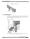
1.11.5 AMP Champ Cable Management
EIAs have cable management eyelets to tiewrap or lace cables to the cover panel. Tie wrap or lace the
AMP Champ cables according to local site practice and route the cables. If you configure the ONS 15454
for a 23-inch (584.2 mm) rack, two additional inches (50.8 mm) of cable management area is available
on each side of the shelf assembly.
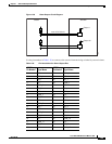
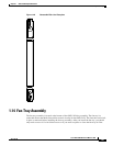
1.12 Alarm Expansion Panel
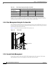
The optional ONS 15454 alarm expansion panel (AEP) can be used with the Alarm Interface
Controller—International card (AIC-I) card to provide an additional 48 dry alarm contacts for the ONS
15454, 32 of which are inputs and 16 are outputs. The AEP is a printed circuit board assembly that is
installed on the backplane. Figure 1-35 shows the AEP board; the left connector is the input connector
and the right connector is the output connector.
The AIC-I without an AEP already contains direct alarm contacts. These direct AIC-I alarm contacts are
routed through the backplane to wire-wrap pins accessible from the back of the shelf. If you install an
AEP, you cannot use the alarm contacts on the wire-wrap pins. For further information about the AIC-I,
see the “2.7 AIC-I Card” section on page 2-27.
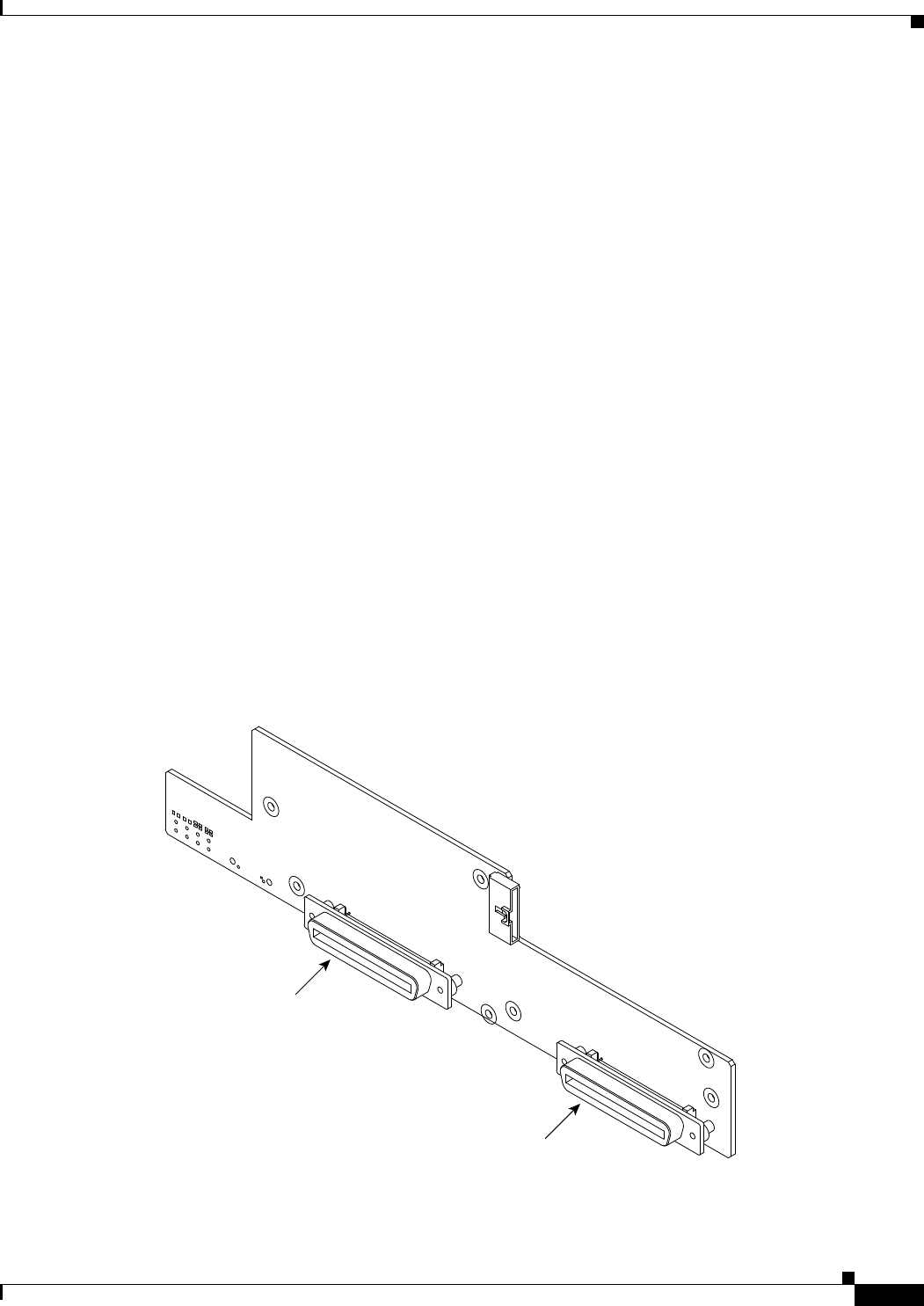
Figure 1-35 AEP Printed Circuit Board Assembly
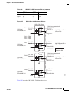
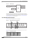
Figure 1-36 shows the AEP block diagram.
78471
Input Connector
Output Connector