


1-56
Cisco ONS 15454 Reference Manual, R7.0
78-17191-01
Chapter 1 Shelf and Backplane Hardware
1.12 1.12.1 Wire-Wrap and Pin Connections
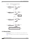
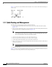
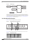
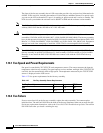
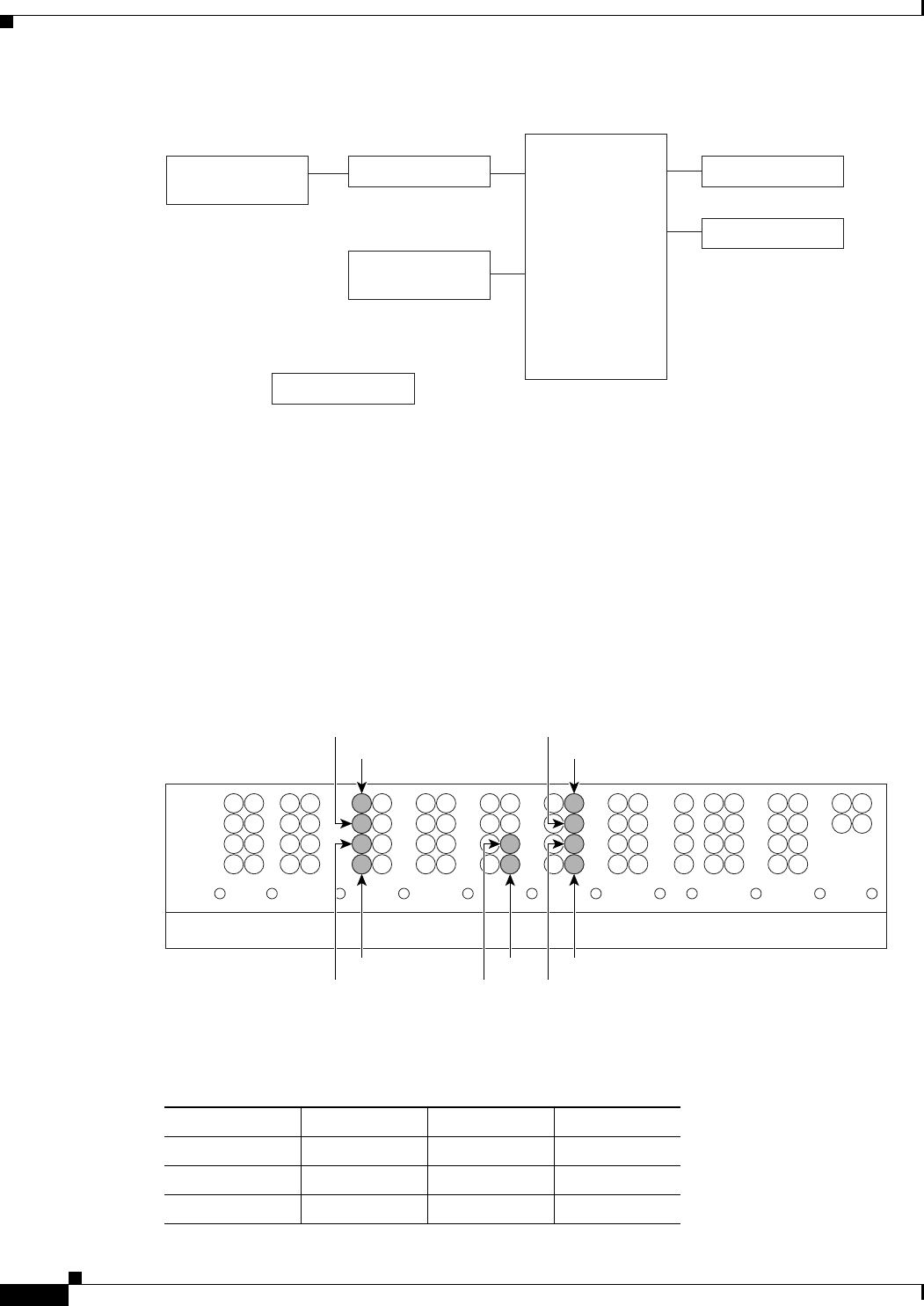
Figure 1-36 AEP Block Diagram
Each AEP alarm input port has provisionable label and severity. The alarm inputs have optocoupler
isolation. They have one common 48-VDC output and a maximum of 2 mA per input. Each opto metal
oxide semiconductor (MOS) alarm output can operate by definable alarm condition, a maximum open
circuit voltage of 60 VDC, anda maximum current of 100 mA. See the “2.7.2 External Alarms and
Controls” section on page 2-29 for further information.
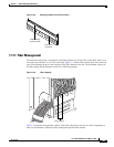
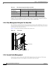
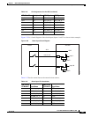
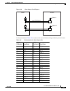
1.12.1 Wire-Wrap and Pin Connections
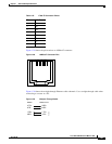
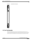
Figure 1-37 shows the wire-wrapping connections on the backplane.
Figure 1-37 AEP Wire-Wrap Connections to Backplane Pins
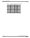
Table 1-24 shows the backplane pin assignments and corresponding signals on the AIC-I and AEP.
AIC-I Interface
(wire wrapping)
TIA/EIA 485 In Alarm Relays
Out Alarm Relays
Inventory data
(EEPROM)
AEP/AIE
CPLD
Power Supply
78406
1
2
3
4
A
FG4FG3FG2FG1
BITS LAN
1
2
3
4
AB
1
2
3
4
AB
IN
1
2
3
4
AB
IN/OUT
FG6FG5
7
8
95
106
ABAB
ENVIRONMENTAL ALARMS
IN
ACO
FG7
1
2
3
4
IN
AB
FG8
1
2
3
4
AB
MODEM
FG9
1
2
3
4
A
CRAFT
AUDVIS
FG10
1
2
3
4
AB
LOCAL ALARMS
IN
FG12FG11
11
12
ABB
96618
White
Black
Blue
Green
Slate
Violet
Orange
Yellow
Red
Brown
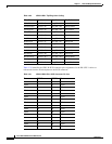
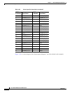
Table 1-24 Pin Assignments for the AEP
AEP Cable Wire Backplane Pin AIC-I Signal AEP Signal
Black A1 GND AEP_GND
White A2 AE_+5 AEP_+5
Slate A3 VBAT– VBAT–