


5-30
Cisco ONS 15454 Reference Manual, R7.0
78-17191-01
Chapter 5 Ethernet Cards
5.12 5.12.1 CE-1000-4 Card-Level Indicators
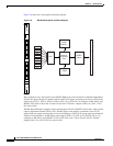
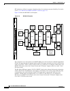
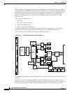
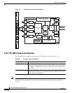
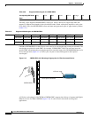
Figure 5-11 CE-1000-4 Faceplate and Block Diagram
5.12.1 CE-1000-4 Card-Level Indicators
The CE-1000-4 card faceplate has two card-level LED indicators, described in Table 5-23.
Note If the CE-1000-4 card is inserted in a slot that has been preprovisioned for a different type of card, the
red FAIL LED and the green ACT LED will flash alternately until the configuration mismatch is
resolved.
145231
1
Rx
Tx
2
Rx
Tx
4
Rx
Tx
3
Rx
Tx
FAIL
ACT
CE-1000-4
ACT/LNK
ACT/LNK
ACT/LNK
ACT/LNK
4 ports:
GigE
GBIC
GBIC
GBIC
GBIC
SERDES
CLOCK Generation
SERDES
SERDES
SERDES
TADM
Malena FPGA
Altera
8260 Processor, SDRAM
Flash and DecodePLD
50MHz,100Mhz
125Mhz,155MHz
BUFFER
MEMORY
CDR
Framer
Quicksilver
FPGA
BTC
192
POWER
5V, 3.3V, 2.5V, 1.8V, -1.7V
-48V
Diff.
Delay.
Mem.
Main RX
BPIA
Protect
TX BPIA
Protect
RX BPIA
Main TX
BPIA
STS48
BACKPLANE
Interface
Table 5-23 CE-1000-4 Card-Level Indicators
Card-Level LEDs Description
FAIL LED (Red) The red FAIL LED indicates that the card processor is not ready or that a
catastrophic software failure occurred on the CE-1000-4 card. As part of the
boot sequence, the FAIL LED is turned on until the software deems the card
operational.
ACT LED (Green) The green ACT LED provides the operational status of the CE-1000-4 card.
When the ACT LED is green, it indicates that the CE-1000-4 card is active
and the software is operational.