


4-8
Cisco ONS 15454 Reference Manual, R7.0
78-17191-01
Chapter 4 Optical Cards
4.3 4.3 OC3 IR/STM1 SH 1310-8 Card
Warning
The laser is on when the optical card is booted. The port does not have to be in service for the laser
to be on.
Statement 293
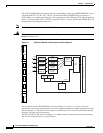
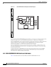
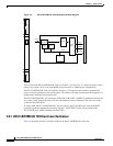
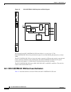
Figure 4-2 shows the card faceplate and block diagram.
Figure 4-2 OC3IR/STM1 SH 1310-8 Faceplate and Block Diagram
You can install the OC3 IR/STM1 SH 1310-8 card in Slots 1 to 4 and 14 to 17. The card can be
provisioned as part of a path protection or in an ADM configuration. Each interface features a 1310-nm
laser and contains a transmit and receive connector (labeled) on the card faceplate. The card uses LC
connectors on the faceplate that are angled downward 12.5 degrees.
The OC3 IR/STM1 SH 1310-8 card supports 1+1 unidirectional and bidirectional protection switching.
You can provision protection on a per port basis.
The OC3 IR/STM1 SH 1310-8 card detects LOS, LOF, LOP, AIS-L, and RDI-L conditions. Refer to the
Cisco ONS 15454 Troubleshooting Guide for a description of these conditions. The card also counts
section and line BIP errors.
To enable APS, the OC3 IR/STM1 SH 1310-8 card extracts the K1 and K2 bytes from the SONET
overhead to perform appropriate protection switches. The OC3 IR/STM1 SH 1310-8 card supports full
DCC/GCC connectivity for remote network management.
uP bus
uPFlash RAM
B
a
c
k
p
l
a
n
e
Optical
Transceiver #1
Optical
Transceiver #2
Optical
Transceiver #3
Optical
Transceiver #4
134369
BPIA RX
Prot
BPIA RX
Main
BPIA TX
Prot
BPIA TX
Main
OCEAN
ASIC
STM-1
STM-1
STM-1
STM-1
Optical
Transceiver #5
Optical
Transceiver #6
Optical
Transceiver #7
Optical
Transceiver #8
STM-1
STM-1
STM-1
STM-1
FAIL
ACT
SF
OC3IR
STM1SH
1310-8