


1-9
Catalyst 2984G, 2948G-GE-TX, and 2980G Switch Hardware Installation Guide
78-6286-05
Chapter 1 Product Overview
Switch Components
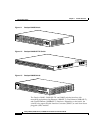
• PSI LED indicates the internal power supply status on the Catalyst 2948G
switch.
• PWR LED indicates the internal power supply status on the Catalyst 2980G
switch.
• RPS LED provides the external redundant power supply status.
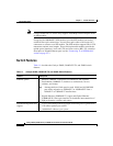
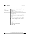
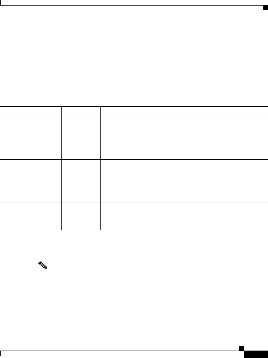
Table 1-2 describes the LEDs.
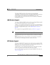
Airflow
Note For environmental specifications, see Chapter 2, “Site Planning.”
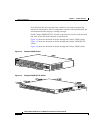
On the Catalyst 2948G and 2980G switches, the system fan assembly provides
cooling air for the internal chassis components. The fans exhaust warm air from
one end and draw in cool air at the other end.
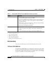
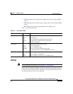
Table 1-2 Front Panel LEDs
LED Color/Statue Description
STATUS Indicates the results of a series of self-test diagnostics.
Green
Red
Amber
Off
All tests pass.
A test other than an individual port test fails.
System boot or diagnostic tests in progress.
Switch is disabled.
Link Status Indicates the link status of a port.
Green
Amber
Flashing
Off
Port is operational.
Port is disabled by user.
Power-on self-test indicates faulty port.
No signal detected, or link configuration failure.
PSI, PWR, and RPS Indicates power supply operation or failure.
Green
Amber
Power supply is operational.
Power supply has failed or is in Standby mode.