


3-17
Catalyst 2984G, 2948G-GE-TX, and 2980G Switch Hardware Installation Guide
78-6286-05
Chapter 3 Installing the Switch
Installing the Catalyst 2948G-GE-TX Switch
Attaching the RPS Connector Cover
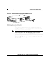
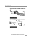
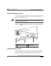
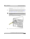
If you are not using a Cisco RPS with your switch, use the two Phillips pan-head
screws to attach the RPS connector cover to the back of the switch before you
mount it, as shown in Figure 3-13.
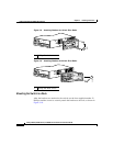
Warning
If an RPS is not connected to the switch, install an RPS connector cover on the
back of the switch.
Statement 265
Figure 3-13 Attaching the RPS Connector Cover on the Catalyst 2948G-GE-TX
Switch
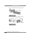
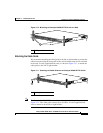
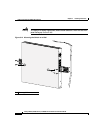
Mounting the Switch on a Wall
For the best support of the switch and cables, make sure the switch is attached
securely to wall studs or to a firmly attached plywood mounting backboard.
Mount the switch with the front panel facing up, as shown in Figure 3-14.
1 Phillips pan-head screws 3 RPS connector
2 RPS connector cover
1 2
R
ATING
100-200V ~
1.6A-0>9A, 50-60 H
Z
DC IN
PU
TS FO
R REM
O
TE
PO
W
ER SUPPLY
SPECIFIED
IN M
ANUAL
+12v @
8.5a
98668
3