


2-5
Catalyst 2984G, 2948G-GE-TX, and 2980G Switch Hardware Installation Guide
78-6286-05
Chapter 2 Site Planning
System Ground Connection Guidelines (Catalyst 2948G and 2980G Switches Only)
• Number 2 Phillips head screwdriver.
• Crimping tool—This must be large enough to accommodate the girth of the
grounding lug when you crimp the grounding cable into the lug.
• Wire-stripping tool.
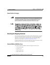
Connecting the Switch to Earth Ground
This procedure describes how to connect the Catalyst 2948G, 2948G-GE-TX,
and 2980G switches to earth ground. We strongly recommend that you complete
this procedure before connecting system power or turning on your switch.
To attach the grounding lug and cable to the grounding pad on the Catalyst 2948G,
2948G-GE-TX, and 2980G switches, follow these steps:
Step 1 Use a wire-stripping tool to remove approximately 0.75 inches (19 mm) of the
covering from the end of the grounding wire.
Step 2 Insert the stripped end of the grounding wire into the open end of the grounding
lug.
Step 3 Use the crimping tool to secure the grounding wire in place in the grounding lug.
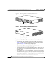
Step 4 Locate the grounding pad on the switch.
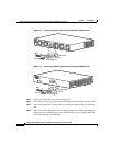
See Figure 2-3 for the location of the grounding pad on the Catalyst 2948G switch
and Figure 2-4 for the Catalyst 2980G switch.