


Chapter 2 Site Planning
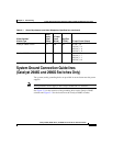
System Ground Connection Guidelines (Catalyst 2948G and 2980G Switches Only)
2-4
Catalyst 2984G, 2948G-GE-TX, and 2980G Switch Hardware Installation Guide
78-6286-05
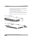
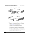
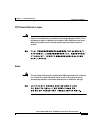
Figure 2-1 Grounding Holes on the Catalyst 2948G Switch
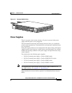
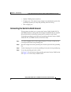
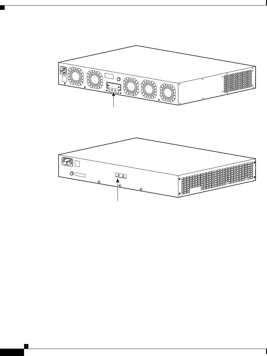
Figure 2-2 Grounding Holes on the Catalyst 2980G Switch
To make an adequate grounding connection, you need these components and
tools:
• Grounding lug—The grounding lug must have two M4 screw holes. See
Figure 2-1 for the location of the M4 screw holes on the Catalyst 2948G
switch and Figure 2-2 for the Catalyst 2980G switch.
The grounding lugs are not available from Cisco Systems; any
electrical-connector vendor can provide this lug.
• Two M4 (metric) hex-head screws with locking washers—These screws are
not available from Cisco Systems; they are available from any commercial
hardware vendor.
• One grounding wire (6 AWG recommended)—The length of the grounding
wires depends on the location of your switch within the site and its proximity
to proper grounding facilities. The grounding wire is not available from Cisco
Systems; it is available from any commercial cable vendor.
M4 screw holes (2)
33110
M4 screw holes (2)
33109