


Chapter 2 Site Planning
System Ground Connection Guidelines (Catalyst 2948G and 2980G Switches Only)
2-6
Catalyst 2984G, 2948G-GE-TX, and 2980G Switch Hardware Installation Guide
78-6286-05
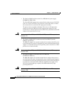
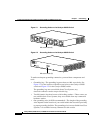
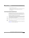
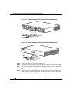
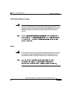
Figure 2-3 Connecting System Ground on the Catalyst 2948G Switch
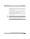
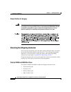
Figure 2-4 Connecting System Ground on the Catalyst 2980G Switch
Step 5
Remove the label that covers the grounding pad.
Step 6 Place the grounding lug against the grounding pad on the rear panel of the switch.
Step 7 Install locking washers; tighten them to secure the grounding lug to the grounding
pad.
Step 8 Insert two screws through the holes in the grounding lug and the grounding pad.
Ensure that the grounding lug and the attached wire will not interfere with other
switch hardware or rack equipment.
33112
Grounding
pad
Grounding lug
Wire
Screws
Grounding
pad
Grounding lug
Wire
Screws
33111