


2-3
Catalyst 2984G, 2948G-GE-TX, and 2980G Switch Hardware Installation Guide
78-6286-05
Chapter 2 Site Planning
System Ground Connection Guidelines (Catalyst 2948G and 2980G Switches Only)
System Ground Connection Guidelines
(Catalyst 2948G and 2980G Switches Only)
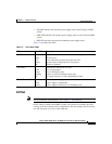
Two system (earth) grounding holes are provided in an enclosure near the power
supplies.
Note These guidelines do not apply to the Catalyst 2948G-GE-TX switches.
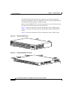
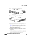
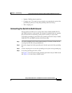
See Figure 2-1 for the location of the grounding holes on the Catalyst 2948G
switches and Figure 2-2 for the location on the Catalyst 2980G switches.
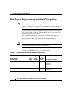
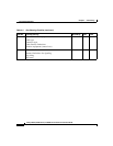
Catalyst 2980G switch 175 300 950 90 VAC: 3.0
120 VAC: 2.4
180 VAC: 1.6
240 VAC: 1.0
Catalyst 2980G-A switch 156 208 670 90 VAC: 2.3
120 VAC: 1.7
180 VAC: 1.1
240 VAC: 0.9
Table 2-1 Power Requirements and Heat Dissipation Specifications (continued)
Model Number/
Module Type
Power
Supply
Output
(Watts)
AC Input
Power
(Watts)
Heat Diss
(BTU/Hr) AC Input Current (Amps)