


1-13
Catalyst 2984G, 2948G-GE-TX, and 2980G Switch Hardware Installation Guide
78-6286-05
Chapter 1 Product Overview
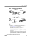
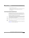
Switch Components
A Cisco RPS can only power one switch at a time. If more than one switch fails
at the same time, any subsequent switch is not supported by the RPS until the first
switch failure is resolved. For more information, refer to the documentation that
was included with your RPS.
On the Catalyst 2948G switch, you must use a Y cable to connect the switch to
two RPS 600 power supplies. Each RPS 600 has status LEDs (PSI and RPS).
On the Catalyst 2980G-A switch, each RPS 300 power supply has an individual
power cord and has status LEDs (PSI, PWR, and RPS).
The RPS uses redundant power supplies. If one of the power supplies in the RPS
fails, the RPS will automatically switch over to the other power supply without
forcing the switch to reboot.
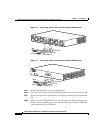
Note On the Catalyst 2948G-GE-TX and 2948G switches, only one power source can
supply power to the switch at any one time. When you are using an RPS, unplug
the local power cord for the switch. If you are using the local power supply, the
RPS can be connected but must not be powered on. The switches can be powered
by both the internal power supply and the RPS at the same time.