


Chapter 1 Introducing the Cisco Wide Area Application Engine
Hardware Features
1-18
Cisco Wide Area Application Engine 511 and 611 Hardware Installation Guide
OL-7220-02
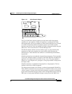
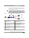
becoming a single point of failure and allows traffic to continue to flow between
the router and the client while it passes through an unresponsive WAE without
being processed.
For more information about configuring the inline network adapter, see the Cisco
Wide Area Application Services Configuration Guide.
Ports and LED Indicators
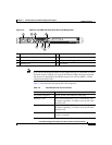
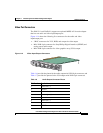
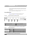
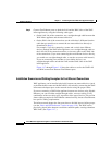
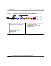
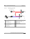
Figure 1-16 shows the inline network adapter port numbers, interface
designations, and LEDs. Table 1-8 describes the LED functions.
Figure 1-16 Inline Network Adapter Port Numbering and LEDs
The inline network adapter has three LEDs that correspond to each port (the 0
LEDs correspond to Port 0, and so forth). Table 1-8 describes the LEDs.
0 Port 0; Group 1 WAN interface 1 Port 1; Group 1 LAN interface
2 Port 2; Group 0 WAN interface 3 Port 3: Group 0 LAN interface
0 1 2 3
LINK/ACT
100
1000
BYPAS
S
0 1 2 3
Table 1-8 Inline Network Adapter LEDs
LEDs State Description
Link / Activity On The 10/100/1000BASE-T interface is receiving power.
Blinking The Ethernet link is transmitting data.
100 On The speed of the Ethernet connection is 100BASE-TX.