


Chapter 1 Introducing the Cisco Wide Area Application Engine
Hardware Features
1-22
Cisco Wide Area Application Engine 511 and 611 Hardware Installation Guide
OL-7220-02
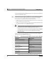
Step 2 Connect Fast Ethernet ports on both the LAN and the WAN sides of the WAE
inline appliance by using the following cable types:
• On the LAN side of the connection, use a straight-through cable between the
WAE inline appliance and the network device.
• On the WAN side of the connection, use the cable that is different from the
cable that you would use to connect the two network devices directly (as
determined in Step 1).
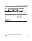
For example, if you are connecting a router and a switch (two different
devices) through the WAE inline appliance, use a straight-through cable on
the LAN side of the connection and use a crossover cable on the WAN side
of the connection. (If you were connecting the two different devices directly,
you would use a straight-through cable, so use the crossover cable instead.)
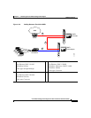
If you are connecting two switches (or two similar devices), use
straight-through cables on both the LAN and the WAN sides of the WAE
inline appliance.
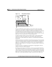
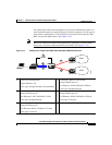
Figure 1-17 through Figure 1-19 show the cables to use for the WAE LAN
and WAN connections between Fast Ethernet ports.
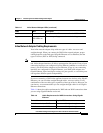
Installation Scenarios and Cabling Examples for Fast Ethernet Connections
WAE appliances can be installed physically between two network devices (such
as the branch office router and branch office LAN switch) by connecting the WAE
inline network adapter ports to the network devices using the proper cables.
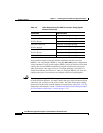
If you are connecting a WAE inline appliance between two devices using Gigabit
Ethernet, you can use either straight-through cables, crossover cables, or any
combination of the two cable types, regardless of the type of device. This section
shows cabling examples for Fast Ethernet connections only, because Fast Ethernet
has specific cabling requirements.
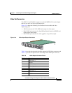
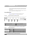
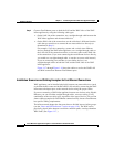
The inline network adapter has four ports that are divided into two inline groups
(see the “Ports and LED Indicators” section on page 1-18). The WAE can be
physically placed inline between two distinct network paths, creating redundant
WAN links. (See Figure 1-17.)