


17
Chassis Ground Connection Installation
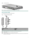
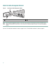
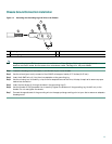
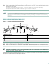
Figure 12 Attaching the Grounding Lug and Wire to the Chassis
Note The grounding lug and Phillips screws are not available from Cisco Systems. Get the grounding lug from an
electrical-connector vendor and the screws from a hardware vendor. See Page 4 for the parts needed.
Step 1 Locate the chassis ground connector (1) on the rear of your router chassis.
Step 2 Use the wire stripper to strip one end of the 6-AWG wire approximately 0.75 inches (19.05 mm).
Step 3 Insert the 6-AWG wire (4) into the wire receptacle on the grounding lug.
Step 4 Use the crimping tool to carefully crimp the wire receptacle around the wire; this step is required to ensure a proper
mechanical connection.
Step 5 Insert the two screws (3) through the holes in the grounding lug (2).
Step 6 Use the Number 2 Phillips screwdriver to carefully tighten the screws until the grounding lug is held firmly to the
chassis. Do not overtighten the screws.
Step 7 Connect the opposite end of the grounding wire to the appropriate grounding point at your site to ensure an adequate
chassis ground.
1
Chassis ground connector
3
Screws
2
Grounding lug
4
Wire
50536
1
2
3
4