


24
Step 2 Ensure that no current is flowing through the DC power supply leads. To ensure that all power is OFF, locate the circuit
breaker on the panel board that services the DC circuit, switch the circuit breaker to the OFF position, and tape the
switch handle of the circuit breaker in the OFF position.
Step 3 Using a wire stripper, strip approximately 0.55 inch (14 mm) from the –V and +V leads.
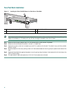
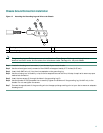
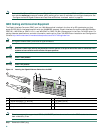
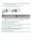
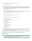
Figure 21 Attaching the Wires to the DC Plug and the DC Plug to the DC Connector
Step 4 To determine which lead to connect to which screw in the DC plug, align the DC plug (1) with the DC connector (4, 5)
in the chassis as shown in the illustration above. Do not insert the plug in the connector. Notice the symbols, + A – ,
embossed on the connector (3). Use the symbols and the orientation of the plug to guide you when inserting the leads
into the plug.
Step 5 Loosen the screws in the DC plug (1), insert the +V and –V leads, and tighten the screws.
Step 6 Insert the DC plug (1) into the DC connector (4) in the chassis.
Step 7 Repeat Step 5 and Step 6 if you have a dual DC power supply (5).
Step 8 Switch the circuit breaker to the ON position
Observe System Startup and Performing a Basic Configuration
Check conditions prior to system startup:
Step 1 Check that all hardware parts and cables are securely attached to the chassis.
Step 2 Check that port adapter configuration information is available, if needed.
Step 3 Check that a CompactFlash Disk is installed.
Step 4 Check that the console terminal is turned on.
1
DC plug
4
Single DC power supply connector
2
Lead
5
Dual DC power supply connectors
3
+ and – embossed on connector
BA
50538
BA
4
5
1
3
2