


4
2 Prepare for Installation
This section contains information about tools and parts, warnings, site preparation information, and information for
workbench or tabletop installation and rack-mount installation.
Warning
Only trained and qualified personnel should install, replace, or service this equipment.
Warning
Read the installation instructions before you connect the system to its power source.
Warning
This unit is intended for installation in restricted access areas. A restricted access area is where access can only
be gained by service personnel through the use of a special tool, lock and key, or other means of security, and is
controlled by the authority responsible for the location.
Before beginning this router installation, read the Cisco 7401ASR Regulatory Compliance and Safety Information.
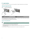
Site Preparation and Unpacking
• Lift the router safely out of the packing container.
• Ensure the power service at the site is suitable for the router you are installing.
• Check the packing slip to ensure that all the proper components are present.
• Locate and have accessible the Site Log for recording information about this installation.
Tools and Parts
Use the following list of tools and parts as a checklist for preparing for installing the Cisco 7401ASR router:
• ESD-preventative wrist strap
• Power cord
• Appropriate cables to connect the router to the network and console terminal
• One serial port adapter cable for each serial port to connect the port with the remote device or network Ethernet transceiver
• Data service unit (DSU) to connect each serial port to an external network
• Tape measure and level
• Screwdrivers: Number 2 Phillips screwdriver and 3/16-inch flat-blade screwdriver
• Grounding lug and wires:
–
A grounding lug with two number-10 screw holes with a 0.63-inch (16.002-mm) spacing between them
–
A wire receptacle large enough to accept a 6-AWG multistrand, copper wire
–
Two Phillips machine screws with locking washers—M5 (metric), 0.031-inch (.08-mm) pitch, 0.315-inch (8-mm) length
–
A crimping tool to fit the grounding lug wire receptacle
–
One grounding wire—6-AWG, 0.162-inch (4.115-mm) diameter, with approximately 0.108-inch (2.743-mm)
insulation, for a total wire diameter of approximately 0.27 inches (6.858 mm). The wire length depends on your router
location and site environment.
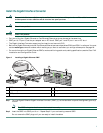
• The rack-mount and cable-management kit:
–
Two rack-mount brackets and one cable management bracket
–
Screws: Four 12-24 x 0.5-inch screws, four 8-18 x .37-inch screws for use with a 19-inch rack, four 8 x .375-inch screws
for use in a 21–23-inch rack, and one M4 x 20-mm screw