


5
• T1 channel service unit/data service unit (CSU/DSU) that converts the High-Level Data Link Control (HDLC) synchronous
serial data stream into a T1 data stream with the correct framing and ones density to connect a serial port to a T1 network.
(Some telephone systems require a minimum number of 1 bits per time unit in a data stream, called ones density.) Several
T1 CSU/DSU devices are available as additional equipment, and most provide a V.35, EIA/TIA-449, or EIA-530 electrical
interface.
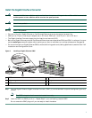
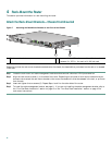
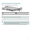
Prepare for Workbench or Tabletop Installation
For a workbench or tabletop installation, verify the following before installing the router:
• The router is off the floor and has adequate ventilation.
• An adequate chassis ground (earth) connection exists for the router.
• The router has at last 3 inches (7.62 cm) of clearance at the inlet and exhaust vents (sides of router).
• The router has 19 inches (48.3 cm) clearance at the front and rear to allow for CompactFlash Disk, Gigabit Interface
Converter (GBIC), and port adapter replacement or installation, or to access cables or equipment.
• The port adapter filler panel is installed if a port adapter is not installed. The slot must not be empty.
For cable-management bracket installation instructions, see page 14.
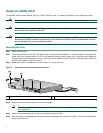
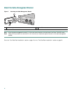
Prepare for Rack-Mount Installation
Make these decisions before you begin the rack-mounting tasks:
• Decide whether or not you want to front- or rear-mount the chassis.
• Decide whether or not you want to attach the cable-management bracket.
• Determine the type of rack—four-post or two-post—that you will be using.
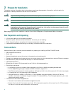
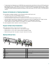
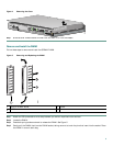
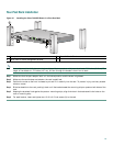
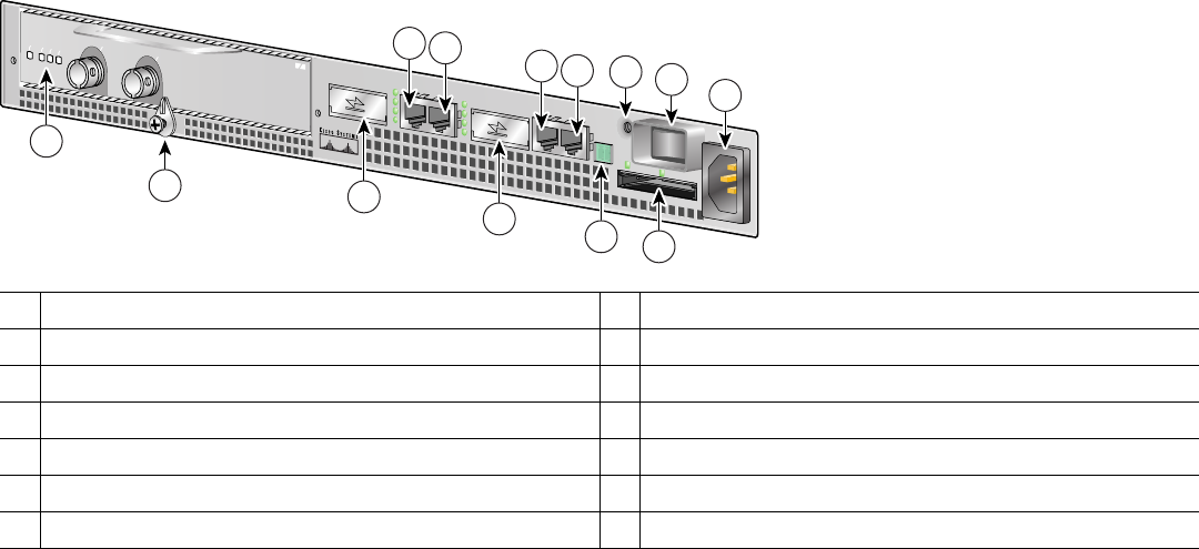
Identify I/O Panel Ports
1
Port adapter slot (installed port adapter shown)
8
Console port
2
Port adapter latch
9
Alarm port
3
GBIC port 0
10
Ground for ESD wrist strap with banana jack
4
FE port 0
11
Power switch
5
FE port 1
12
CompactFlash Disk slot
6
GBIC port 1
13
Power connector
7
Auxiliary port
57606
ENABLED
RX CELLS
RX CARRIER
RX ALARM
TX
RX
ENHANCED ATM
13
10
1
2
9
7
12
6
8
4
5
11
3