


19
For more information, see the online Cisco 7401ASR Installation and Configuration Guide.
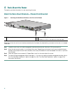
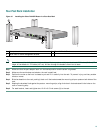
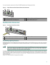
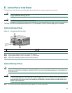
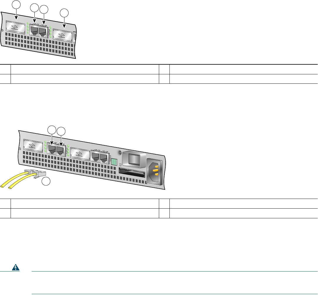
Figure 14 Gigabit Ethernet and Fast Ethernet/Ethernet Port Identification
Fast Ethernet RJ-45 Connections
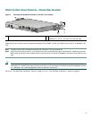
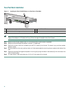
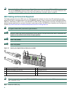
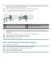
Figure 15 Attaching the Fast Ethernet Cables
Intra-Building Lightning Protection
Shielded cables which are grounded at both ends are required to be used on the 10/100 Ethernet port in order to be in compliance
with requirement R4-11 in GR-1089-Core for a Central Office environment. This is not a requirement for customer premise
installations.
Warning
To avoid electric shock, do not connect safety extra-low voltage (SELV) circuits to telephone-network voltage
(TNV) circuits. LAN ports contain SELV circuits, and WAN ports contain TNV circuits. Some LAN and WAN ports
both use RJ-45 connectors. Use caution when connecting cables.
To identify the RJ-45 cable type, hold the two ends of the cable next to each other so you can see the colored wires inside the
ends. The straight-through wire type has colored wires in the same sequence at both ends. In the crossover wire type, the first
colored wire at the far left is the third colored wire at the other end. The second colored wire at the far left is the sixth colored
wire at the other end.
Attach RJ-45 Ethernet cables to the appropriate connector.
1
Gigabit Ethernet (GBIC) port 0
3
Fast Ethernet/Ethernet (100 Mbps) port 1
2
Fast Ethernet/Ethernet (100 Mbps) port 0
4
Gigabit Ethernet (GBIC) port 1
1
Fast Ethernet/Ethernet port 0—RJ-45 connector
3
Fast Ethernet/Ethernet cables
2
Fast Ethernet/Ethernet port 1—RJ-45 connector
57832
1
2
3
4
5
7696
1
2
3