


22
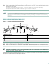
Port Adapter Cable Connections
The instructions for connecting the cables for each port adapter installed in the Cisco 7401ASR router are in the respective
online note for each port adapter. The documents are available on the Documentation CD-ROM and on Cisco.com at
http://www.cisco.com/univercd/cc/td/doc/product/core/7200vx/portadpt/index.htm. Also see the release notes for any
information about a specific port adapter. Release notes are found at
http://www.cisco.com/univercd/cc/td/doc/product/software/index.htm.
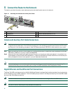
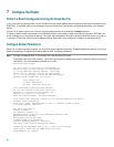
Alarm Port Connection
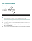
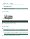
Figure 18 Connecting the Alarm Port Cable
Connect the dry relay alarm port cable connector to the alarm port. It cannot be inserted incorrectly. The dry relay alarm port
operates at 50V AC/DC maximum and up to 80 mA maximum. Total power dissipation should not exceed 300 milliwatts. The
normally closed position will have from 15 to 30 ohms resistance. The open position will be greater than 1 megohom. The alarm
condition is the closed position. This port is a switch so that the cable connector can be inserted in either orientation.
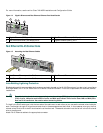
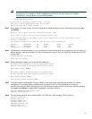
Cable Management
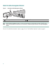
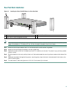
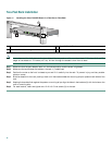
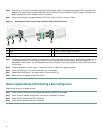
Figure 19 Inserting the Cables Through the Cable-Management Bracket
If you have not already done so, run the port adapter and input/output cables through the cable-management bracket.
1
Alarm port
1
Input/output cables
2
Cable-management bracket
57725
1
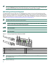
ENABLED
RX CELLS
RX CARRIER
RX ALARM
TX
RX
ENHANCED ATM
57581
1
2