


5
Installing and Upgrading Internal Modules in Cisco 2800 Series Routers
OL-5792-04
Removing the Chassis Cover
Step 4 Perform the following steps to loosen the cover from the chassis:
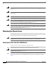
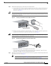
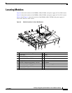
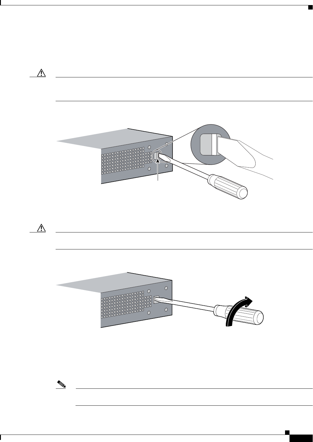
a. Insert the blade of a 1/4-inch screwdriver straight into the square hole on either side of the chassis
near the rear, so that it bottoms against the chassis and does not go past the chassis and into the
narrow slot. See Figure 4.
Caution Make sure that the tip of the screwdriver does not slide into the narrow vertical slot that is visible inside
the square hole. The tip of the screwdriver should rest on the metal tab just inside the chassis cover and
to the right of the vertical slot.
Figure 4 Inserting the Screwdriver into the Side of the Chassis
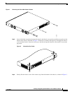
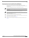
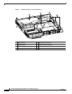
b. With the screwdriver positioned as required in Step a. above, rotate the screwdriver a quarter turn
toward the rear of the chassis to loosen one side of the cover. See Figure 5.
Caution The friction fit may be fairly tight; however, if the cover does not move with moderate effort, make sure
that the screwdriver is not inserted into the narrow vertical slot.
Figure 5 Rotating the Screwdriver to Loosen the Chassis Cover
c.
Repeat Step a. and Step b. for the opposite side of the chassis.
The cover should now be positioned back from the bezel about 1/4 inch (6 to 7 mm). If it is not,
repeat Step a. and Step b. for one or both sides of the chassis.
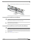
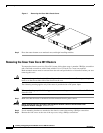
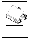
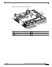
Step 5 Slide the cover toward the rear of the chassis until it contacts a stop (about 1 inch [25 mm]) and the front
edge of the cover is free. See Figure 6.
Note After the cover is loosened as in Step 4, there may still be some friction to overcome as you
complete the removal. However, do not use the screwdriver again as in Step 4.
103860
Screwdriver must not
enter the vertical slot
103861