


14
Chassis Installation Procedures for Cisco 2800 Series Routers
OL-5786-03
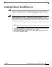
Installing the Chassis Ground Connection
To install the ground connection for a Cisco 2800 series router, perform the following steps:
Step 1 Strip one end of the ground wire to the length required for the ground lug or terminal.
• For the NEBS ground lug—approximately 0.75 in. (20 mm)
• For user-provided ring terminal—as required
Step 2 Crimp the ground wire to the ground lug or ring terminal, using a crimp tool of the appropriate size.
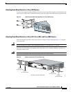
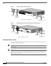
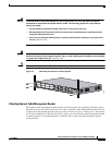
Step 3 Attach the ground lug or ring terminal to the chassis as shown in Figure 17, Figure 18, Figure 19,
Figure 20, or Figure 21. For a ground lug, use the two screws with captive locking washers provided. For
a ring terminal, use one of the screws provided. Tighten the screws to a torque of 8 to 10 in-lb
(0.9 to 1.1 N-m).
Step 4 Connect the other end of the ground wire to a known reliable earth ground point at your site.
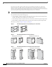
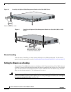
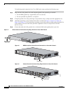
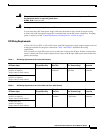
Figure 17 Chassis Ground Connection Using Ring Terminal on Cisco 2801 Chassis
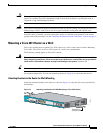
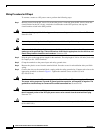
Figure 18 NEBS-Compliant Chassis Ground Connection on Cisco 2811 Chassis
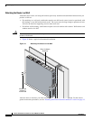
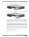
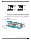
Figure 19 Chassis Ground Connection Using Ring Terminal on Cisco 2811 Chassis
117082
Ring terminal
attachment
98808
Ground lug
A= ACT
FE 0/1
PVDM1 PVDM0 AIM1
AIM0
FE 0/0
S= SPEED
A= FDX
A= LINK
A
F
S
L
A
F
S
L
S
L
O
T
2
S
L
O
T
0
S
L
O
T
3
S
L
O
T
1
ENM0
103066
A= ACT
FE 0/1
PVDM1
PVDM0 AIM1
AIM0
FE 0/0
S= SPEED
A= FDX
A= LINK
A
F
S
L
A
F
S
L
S
L
O
T
2
S
L
O
T
0
S
L
O
T
3
S
L
O
T
1
ENM0
Ring terminal
attachment