


49
Installing and Upgrading Internal Modules in Cisco 2800 Series Routers
OL-5792-04
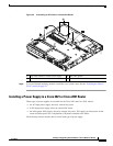
Replacing the Power Supply
Installing an ILP Supply
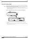
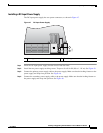
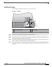
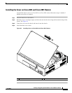
The ILP supply has three power connectors, as shown in Figure 49.
Figure 49 ILP Supply
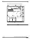
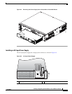
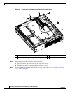
Step 1 Insert the AC-input power supply into the chassis from the front.
Step 2 Install the two power supply retaining screws. Torque to 8 to10 in-lbf (0.9 to 1.1 N-m). See Figure 43.
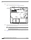
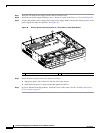
Step 3 Connect the primary power supply cable to the power supply. Make sure that the locking feature on the
power supply end snaps into position. See Figure 46.
Step 4 Connect the secondary power supply cable to the power supply. Make sure that the locking feature on
the power supply end snaps into position. See Figure Figure 48.
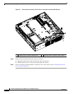
Step 5 Connect the ILP cable to the supply. Make sure that the locking feature on the power supply end snaps
into position. You must also route the ILP cable through the hooks on the power supply and chassis.. See
Figure 50.
1 Primary power connector 3 ILP connector
2 Secondary power connector
127782
1
3
2