


46
Installing and Upgrading Internal Modules in Cisco 2800 Series Routers
OL-5792-04
Replacing the Power Supply
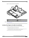
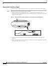
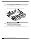
Step 1 Insert the AC-input power supply into the chassis from the front.
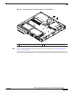
Step 2 Install the two power supply retaining screws. Torque to 8 to10 in-lbf (0.9 to 1.1 N-m). See Figure 43.
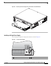
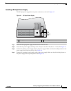
Step 3 Connect the primary power supply cable to the power supply. Make sure that the locking feature on the
power supply end snaps into position. See Figure 46.
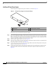
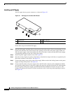
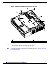
Figure 46 Primary Power Cable Connection in a Cisco 2821 or Cisco 2851 Router
.
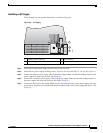
Step 4 Install the bezel onto the front of the chassis as follows:
a. Engage the plastic tabs of the bezel into the slots in the chassis.
b. Slide the bezel until it is centered and tight against the chassis.
Step 5 If you are finished installing modules, install the cover on the router. See the “Installing the Chassis
Cover” section on page 51.
1 Power supply 2 Primary power cable connector
103705
1
2