


29
Installing and Upgrading Internal Modules in Cisco 2800 Series Routers
OL-5792-04
Installing and Removing PVDMs
PVDM Location and Orientation
The PVDM connectors are located on the system board, and are identified as follows:
• In Cisco 2801 and Cisco 2811 routers—PVDM 0 and PVDM 1
• In Cisco 2821 and Cisco 2851 routers—PVDM 0, PVDM 1, and PVDM 2
Refer to Figure 8, Figure 9, Figure 10, and Figure 11 for PVDM locations.
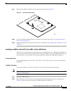
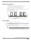
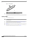
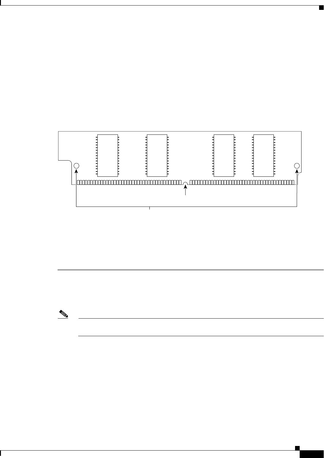
PVDMs have a polarization notch on the mating edge to prevent incorrect insertion. Figure 28 shows the
polarization notch on a PVDM.
Figure 28 PVDM Showing Polarization Notch
Removing a PVDM
To remove a PVDM from the system board, follow these steps:
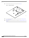
Step 1 Locate the PVDM on the system board. See Figure 8, Figure 9, Figure 10, or Figure 11, depending on
your router model, for the location of the PVDMs.
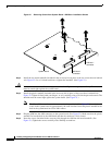
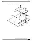
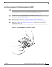
Step 2 Pull the PVDM retaining clips away from the PVDM at both ends, and then tilt the PVDM until it can
be freely removed from the connector. See Figure 29.
Note PVDMs must be removed in order—PVDM 1 then PVDM 0 in Cisco 2801 and 2811 routers, and
PVDM 2, then PVDM 1, then PVDM 0 in Cisco 2821 and 2851 routers.
Polarization notch
103363
Alignment holes