


13
Overview of Cisco 2800 Series Routers
OL-5783-01
Chassis Views
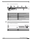
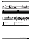
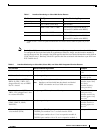
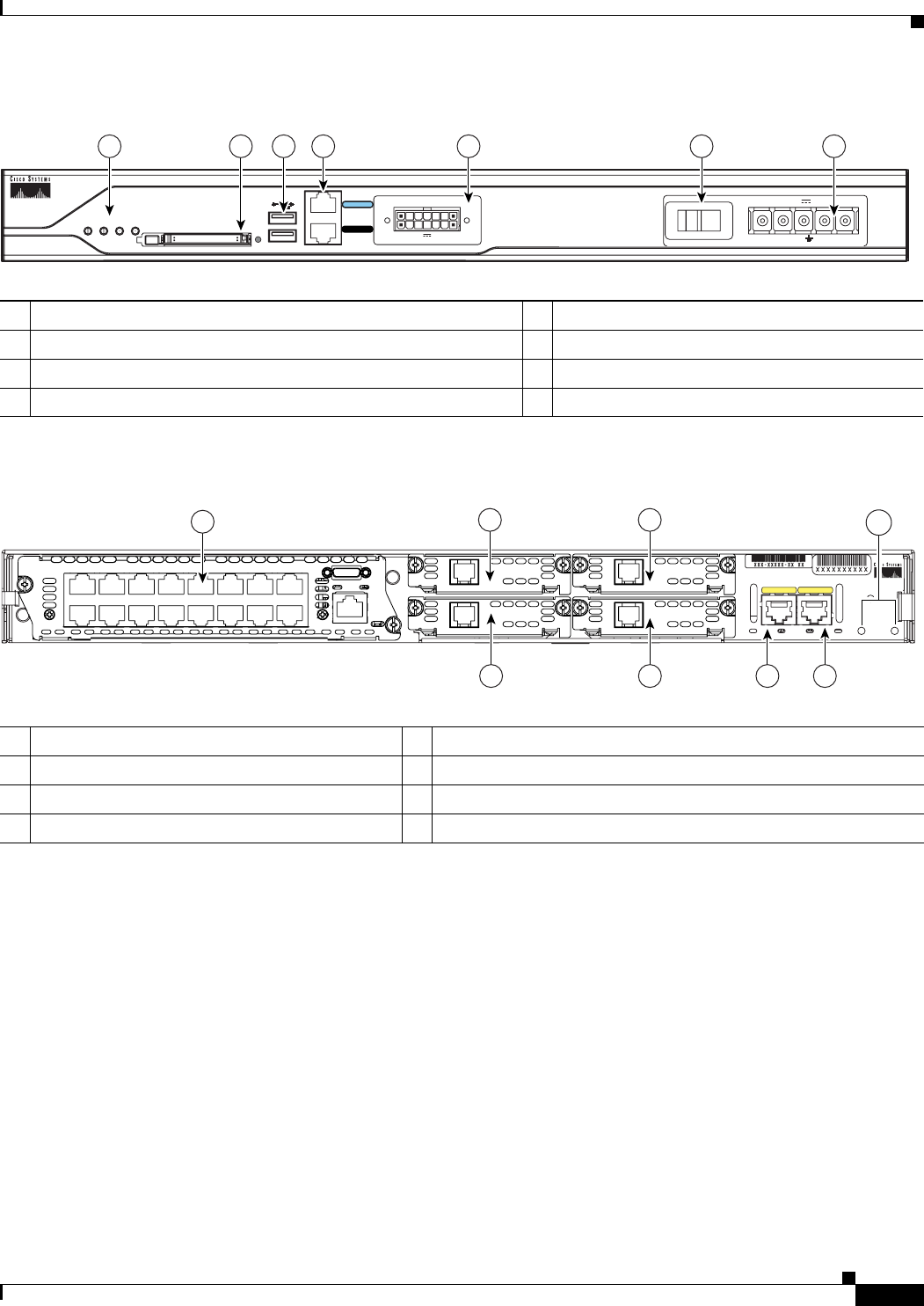
Figure 11 Front Panel of Cisco 2811 Router with DC Input Power
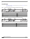
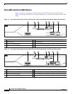
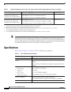
Figure 12 Rear Panel of Cisco 2811 Router
1 Input power connection 5 Universal serial bus (USB) ports
2 On/Stand-by switch
1
1. This switch does not turn off the power supply completely, but rather puts it in stand-by mode.
6 External CompactFlash memory card slot
3 Cisco redundant power supply connector (covered if not used) 7 LED indicators
4 Console and auxiliary ports
1 Screw holes for ground lug 5 High-speed WAN interface card slot 1
2 Fast Ethernet port 0/0 6 High-speed WAN interface card slot 2
3 Fast Ethernet port 0/1 7 High-speed WAN interface card slot 3
4 High-speed WAN interface card slot 0 8 Network module enhanced (NME) slot
1
1. The network module slot is compatible with Cisco network modules of type NM (network module) and NME (network module enhanced).
95552
Do Not Remove During Network Operation
COMPACT FLASH
CONSOLE
0
1
OPTIONAL RPS INPUT
12V 11A
AUX
SYS
PWR
AUX/
PWR
SYS
ACT CF
4567 3
24-60 V 8A
12
A= ACT
FE 0/1
PVDM1 PVDM0 AIM1 AIM0
FE 0/0
S= SPEED
A= FDX
A= LINK
A
F
S
L
A
F
S
L
H
W
I
C
2
H
W
I
C
0
H
W
I
C
3
H
W
I
C
1
1
23
95556
45
67
1
8