


12
Overview of Cisco 2800 Series Routers
OL-5783-01
Chassis Views
Cisco 2811 Chassis
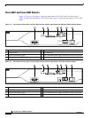
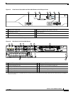
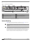
Figure 9, Figure 10, and Figure 11 show the front panel of a Cisco 2811 router. Figure 12 shows the rear
panel of a Cisco 2811 router.
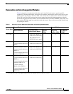
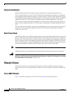
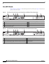
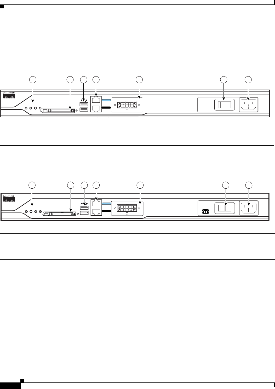
Figure 9 Front Panel of Cisco 2811 Router with AC Input Power and Without IP Phone Power Output
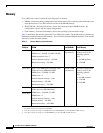
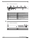
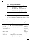
Figure 10 Front Panel of Cisco 2811 Router with AC Input Power and with IP Phone Power Output
1 Input power connection 5 Universal serial bus (USB) ports
2 On/Off switch 6 External CompactFlash memory card slot
3 Cisco redundant power supply connector (covered if not used) 7 LED indicators
4 Console and auxiliary ports
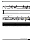
1 Input power connection 5 Universal serial bus (USB) ports
2 On/Off switch 6 External CompactFlash memory card slot
3 Cisco redundant power supply connector (covered if not used) 7 LED indicators
4 Console and auxiliary ports
95551
Do Not Remove During Network Operation
COMPACT FLASH
CONSOLE
0
1
OPTIONAL RPS INPUT
12V 11A
AUX
SYS
PWR
AUX/
PWR
SYS
ACT CF
100-240 V~ 2A
50/60 Hz
124567 3
95550
CONSOLE
OPTIONAL RPS INPUT
12V 11A
AUX
SYS
PWR
AUX/
PWR
SYS
ACT CF
-48V 4A
124567 3
0
1
100-240V~ 8A
50/60 Hz
Do Not Remove During Network Operation
COMPACT FLASH