


40
Installing and Upgrading Internal Modules in Cisco 2800 Series Routers
OL-5792-04
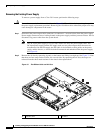
Replacing the Power Supply
Installing an ILP Supply
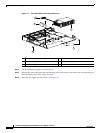
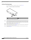
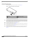
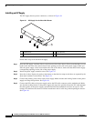
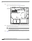
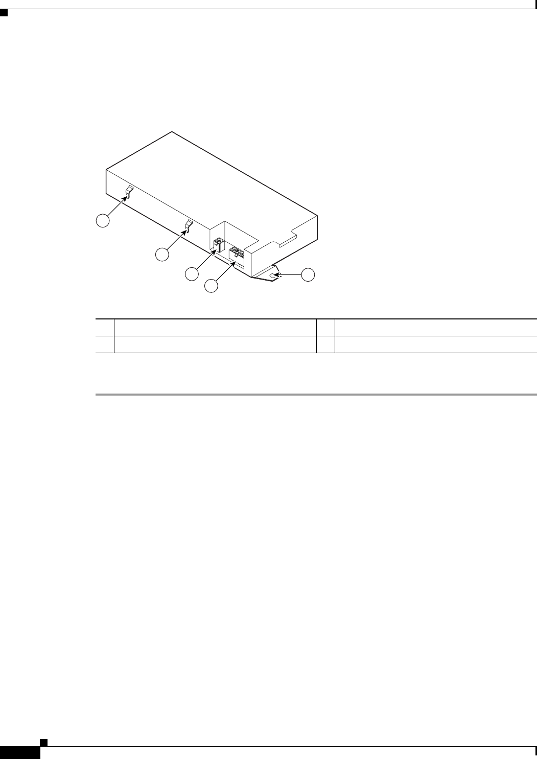
The ILP supply has two power connectors, as shown in Figure 39.
Figure 39 ILP Supply for the Cisco 2811 Router
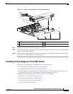
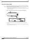
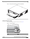
Follow these steps to install the ILP supply.
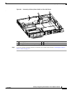
Step 1 Insert the ILP supply, and then slide it to the front and side of the chassis. Please note that there are two
hooks inside the front of the chassis that fit into openings on the side of the power supply. When you
slide the power supply to the front and then the side of the chassis, make sure that these hooks engage
corresponding openings on the side of the power supply.
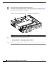
Step 2 Install the power supply retention screw. See Figure 34.
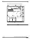
Step 3 Insert the air duct. Squeeze it gently at the bottom so that the four snaps on the duct are captured by the
sheet metal retainers in the chassis. See Figure 33.
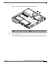
Step 4 Connect the primary power cable to the power supply. Make sure that the locking feature on the power
supply end snaps into position. See Figure 36.
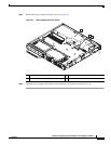
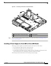
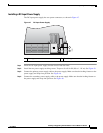
Step 5 Connect the ILP cable to the power supply and to the ILP cable connector on the motherboard. Make
sure that the locking feature on the power supply end snaps into position. Route the ILP cable through
the cable guides on the power supply, aroiund and under the motherboard and not on top of it. This
routing will minimize the chance of airflow interference and of cable snags when opening the chassis.
See Figure 40.
1 Retention tab 3 ILP connector
2 Primary power connector 4 ILP cable guides
135277
1
2
3
4
4