


30
Installing and Upgrading Internal Modules in Cisco 2800 Series Routers
OL-5792-04
Installing and Removing PVDMs
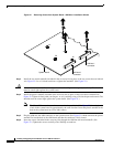
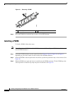
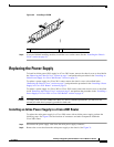
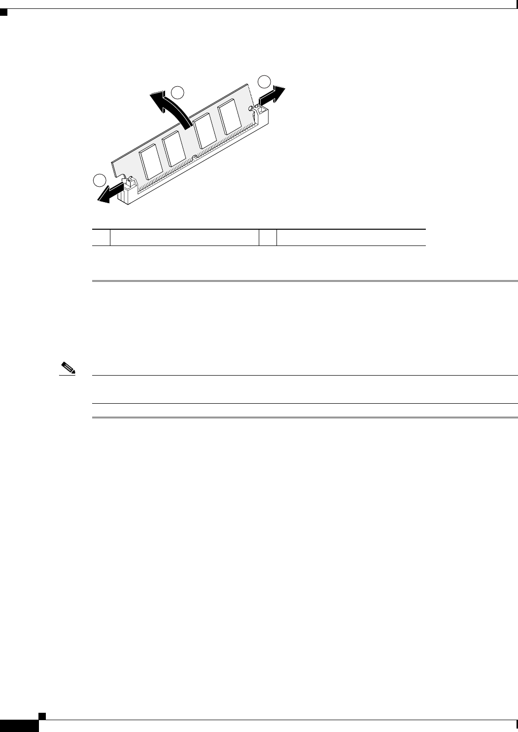
Figure 29 Removing a PVDM
Step 3
Place the PVDM in an antistatic bag to protect it from ESD damage.
Installing a PVDM
To install a PVDM, follow these steps.
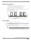
Note If installing only one PVDM, install it in PVDM connector 0. If installing two PVDMs, install the second
one in PVDM connector 1.
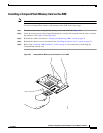
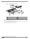
Step 1 Locate the PVDM connector on the system board. See Figure 8, Figure 9, Figure 10, or Figure 11,
depending on your router model, for the location of the PVDM connectors.
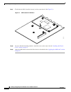
Step 2 Orient the PVDM so that the polarization notch lines up with the polarization key on the connector. See
Figure 28.
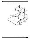
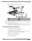
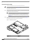
Step 3 Hold the PVDM at an angle and insert it carefully into the PVDM connector. Tilt the PVDM up to the
vertical position so that the clips snap into place at both ends. See Figure 30.
1 Release clips 2 Tilt the PVDM
103468
1
1
2