


12
Cable Connection Procedures for Cisco 2800 Series Routers
OL-5787-02
Connecting to a Console Terminal or Modem
Connection Procedures and Precautions
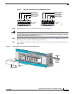
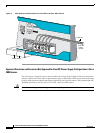
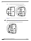
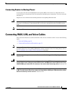
Connect each WAN, LAN, and voice cable to the appropriate connector on the chassis or on a network
module or interface card.
• Position the cables carefully, so that they do not put strain on the connectors.
• Organize cables in bundles so that cables do not intertwine.
• Inspect the cables to make sure that the routing and bend radiuses are satisfactory. Reposition cables,
if necessary.
• Install cable ties in accordance with site requirements.
For cable pinouts, refer to the Cisco Modular Access Router Cable Specifications document.
Connecting to a Console Terminal or Modem
Your router has asynchronous serial console and auxiliary ports for system management. These ports
provide administrative access to your router either locally (with a console terminal or PC) or remotely
(with a modem).
Cisco provides the following cables for connecting your router to a console terminal, PC, or modem:
• One console cable (RJ-45-to-DB-9, blue)
• One modem cable (RJ-45-to-DB-25, black) (Cisco 2811, Cisco 2821, and Cisco 2851 only)
• One DB-9-to-DB-25 adapter (Cisco 2801 only)
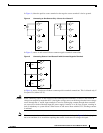
This section describes how to connect a console terminal or PC to the console port and how to connect
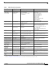
a modem to the auxiliary port. Table 4 summarizes the system management connections.
For information about cable pinouts, refer to the Cisco Modular Access Router Cable Specifications
document.
Table 4 System Management Connections
Port Color Connected To: Cable
Console Light blue PC or ASCII terminal communication port
(usually labeled COM)
RJ-45-to-DB-9 console cable
Auxiliary Black Modem for remote access RJ-45-to-DB-25 modem cable or
RJ-45-to-DB-9 console cable with a
DB-9-to-DB25 adapter