


31
Installing and Upgrading Internal Modules in Cisco 2800 Series Routers
OL-5792-04
Replacing the Power Supply
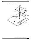
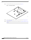
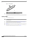
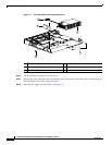
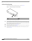
Figure 30 Installing a PVDM
Step 4
If you are finished installing modules, install the cover on the router. See the “Installing the Chassis
Cover” section on page 51.
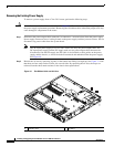
Replacing the Power Supply
To install an inline power (ILP) supply in a Cisco 2801 router, remove the chassis cover as described in
the “Removing the Chassis Cover” section on page 2, and perform the procedure in the “Installing an
Inline Power Supply in a Cisco 2801 Router” section on page 31.
To replace a power supply in a Cisco 2811 router, remove the chassis cover as described in the
“Removing the Chassis Cover” section on page 2, and perform the procedure in the “Installing a Power
Supply in a Cisco 2811 Router” section on page 33.
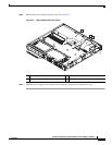
To replace a power supply in a Cisco 2821 or Cisco 2851 router, remove the chassis cover as described
in the “Removing the Chassis Cover” section on page 2, and perform the procedure in the “Installing a
Power Supply in a Cisco 2821 or Cisco 2851 Router” section on page 41.
Caution To comply with Telcordia NEBS GR-1089-Core and EN 300386 requirements, you must use foil
twisted-pair cable that is properly grounded at both ends.
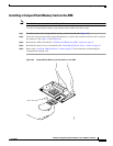
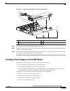
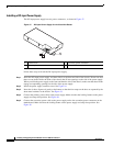
Installing an Inline Power Supply in a Cisco 2801 Router
To replace the main power supply in a Cisco 2801 router with an inline power supply, perform the
following steps. See Figure 8 for the locations of connectors and other components within the
Cisco 2801 router.
Step 1 Disconnect the power supply cable from the main power supply connector.
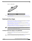
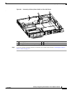
Step 2 Remove the screws that fasten the main power supply to the chassis. See Figure 31.
1 Tilt PVDM up to vertical 2 Clips snap into place
103469
2
2
1