


Chapter 6 Cabling the Line Ports and Completing the Installation
Installing a Cascaded System
Cisco SCE 2000 4xGBE Installation and Configuration Guide
OL-7824-04 6-11
Step 2 Connect both SCE 2000 platforms to the management station. (See Connecting the Management
Interface (on page 5-25).)
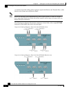
Step 3 Connect the cascade ports. (See Dual Link: Two SCE 2000s Topology (on page 6-5).)
Step 4 Set topology configurations for each SCE 2000 platform via the connection-mode options. (See
Topology-Related Parameters for Redundant Topologies (on page 6-11).)
Step 5 Make sure that the SCE 2000 platforms have synchronized and active SCE 2000 platform was
selected.
Use the show interface linecard 0 connection-mode command.
Step 6 If you want to start with bypass/sniffing, change the link mode to your required mode in both
SCE 2000 platforms on both links. The bypass mode will be applied only to the active SCE 2000
platform. (See Link Mode (on page 6-13).)
Step 7 Make sure that the link mode is as you required. (See Monitoring the System (on page 6-14).)
Use the show interface linecard 0 link mode command.
Step 8 Connect the traffic port of SCE 2000 platform #1. This will cause a momentary down time until
the network elements from both sides of the SCE 2000 platform auto-negotiate with it and start
working (when working inline). (See Dual Link: Two SCE 2000s Topology (on page 6-5).)
Step 9 Connect the traffic port of SCE 2000 platform #2, this will cause a momentary down time until
the network elements from both sides of the SCE 2000 platform auto-negotiate with it and start
working (when working inline). (See Dual Link: Two SCE 2000s Topology (on page 6-5).)
Step 10 When full control is needed, change the link mode on both SCE 2000 platforms on both links to
‘forwarding’. It is recommended to first configure the active SCE 2000 platform and then the
standby. (See Link Mode (on page 6-13).)
Step 11 You can now start working with the Subscriber Manager.
CLI Commands
This section presents CLI commands relevant to the configuration and monitoring of a redundant
system.
Use the following commands to configure and monitor a redundant system:
• connection-mode
• [no] force failure-condition
• Show interface linecard 'number' connection-mode
• Show interface linecard 'number' physically-connected links
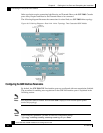
Topology-Related Parameters for Redundant Topologies
All four of the topology-related parameters are required when configuring a redundant topology.
• Connection mode — Redundancy is achieved by cascading two SCE 2000 platforms.
Therefore the connection mode for both SCE 2000 platforms may be either:
• Inline-cascade