


Chapter 5 Connecting the Management Interfaces and Performing Initial System Configuration
Initial System Configuration
Cisco SCE 2000 4xGBE Installation and Configuration Guide
5-20 OL-7824-04
The procedure described below is a presentation of all the questions in the topology configuration.
In actual practice, all questions may not be presented for a particular configuration, depending on
the topology deployed.
Study the examples that follow to understand the procedure for various topologies.
To configure topology dependent parameters, complete the following steps:
Step 1 Enter the topology configuration menu.
Would you like to enter the Topology configuration menu? [no]: y
Type y and press Enter.
The topology configuration dialog begins.
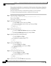
Step 2 Specify the connection mode.
• To define inline connection mode, press Enter.
• To define receive-only connection mode, type 2 and press Enter.
Enter Connection mode:
1- inline
2- receive-only
Enter your choice [1]:
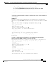
Step 3 Specify the deployment type.
• To specify a Single-SCE Platform deployment, press Enter.
• To specify a Cascade deployment, type y and press Enter.
Is this a cascade deployment? [no]:
Step 4 Specify the physically-connected-link index.
• To specify link-0, press Enter.
• To specify link-1, type 1 and press Enter.
Enter Physically connected link:
0- link-0
1- link-1
Enter your choice [0]:
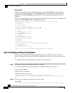
Step 5 Specify the SCE 2000 priority.
• To specify Primary, press Enter.
• To specify Secondary, type 2 and press Enter.
Enter SCE 2000 priority:
1- primary
2- secondary
Enter your choice [1]:
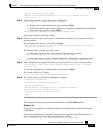
Step 6 Specify the On-failure link behavior.
• To specify Bypass, press Enter.
• To specify Cutoff, type 2 and press Enter.
Enter On-failure behavior:
1- bypass
2- cutoff
Enter your choice [1]:
Step 7 Specify the status of the SCE 2000 after abnormal boot.