


Chapter 2 Introduction to the SCE Platform
Front Panel
Cisco SCE 2000 4xGBE Installation and Configuration Guide
2-2 OL-7824-04
Front Panel
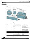
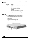
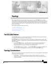
The SCE 2000 Front Panel consists of ports and LEDs as shown in the following figure and
tables.
Figure 2-1: SCE 2000 Front Panel
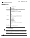
Table 2-2 SCE 2000 Ports
Port Quantity Description Connect This Port To…
Mng1/
Mng2
2 10/100/1000 Ethernet RJ-45 ports for
management of the SCE 2000.
CLI designation: interface Management
0/1, 0/2.
A LAN using an FE cable
with an RJ-45 connector.
If both interfaces are used to
provide a redundant
management interface,
connect both ports to the LAN
via a switch.
Console 1 RS-232 RJ-45 port for use by technicians A local terminal (console)
using an RS-232 cable with
an RJ-45 connector, as
provided in the SCE 2000 kit.
AUX 1 RS-232 RJ-45 port used by technicians
GBE ports 1-4 4 GigabitEthernet SC ports for connecting
to the line and/or cascading two devices
CLI designation: interface
GigabitEthernet 0/1 through 0/4
Refer to Connecting the Line
Ports (on page 6-1) for
cabling diagrams for various
topologies