


Appendix A The External Optical Bypass Module
Installing the External Bypass Module
Cisco SCE 2000 4xGBE Installation and Configuration Guide
OL-7824-04 A-5
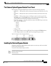
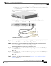
• Connect the control cable to the Bypass 2 9-pin D-Type connector on the rear panel of the
SCE 2000 platform.
Figure A-4: Bypass Connectors on the Rear of the SCE 2000
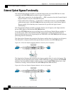
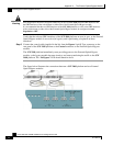
The following figure illustrates the connectivity of the External Optical Bypass module.
To cable the External Optical Bypass module:
Step 1 Connect an optical cable (user supplied) between the GBE port on the Subscriber side network
element and the SUB port on the External Optical Bypass module.
Step 2 Connect an optical cable (user supplied) between the GBE port on the Network side network
element and the NET port on the External Optical Bypass module.
Verify that the links between the two network elements are active.
Step 3 Connect the SUB cable of the fiber of the External Optical Bypass module to the SUB GBE port
of the SCE 2000 platform.
Rx <-> Tx
Step 4 Connect the NET cable of the fiber of the External Optical Bypass module to the NET GBE port
of the SCE 2000 platform.
Rx <-> Tx
Step 5 Power up the SCE 2000 platform, as explained in Starting the System and Observing Initial
Conditions (on page 7-2).