


Chapter 2 Introduction to the SCE Platform
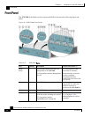
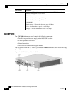
Front Panel
Cisco SCE 2000 4xGBE Installation and Configuration Guide
OL-7824-04 2-3
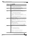
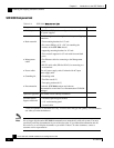
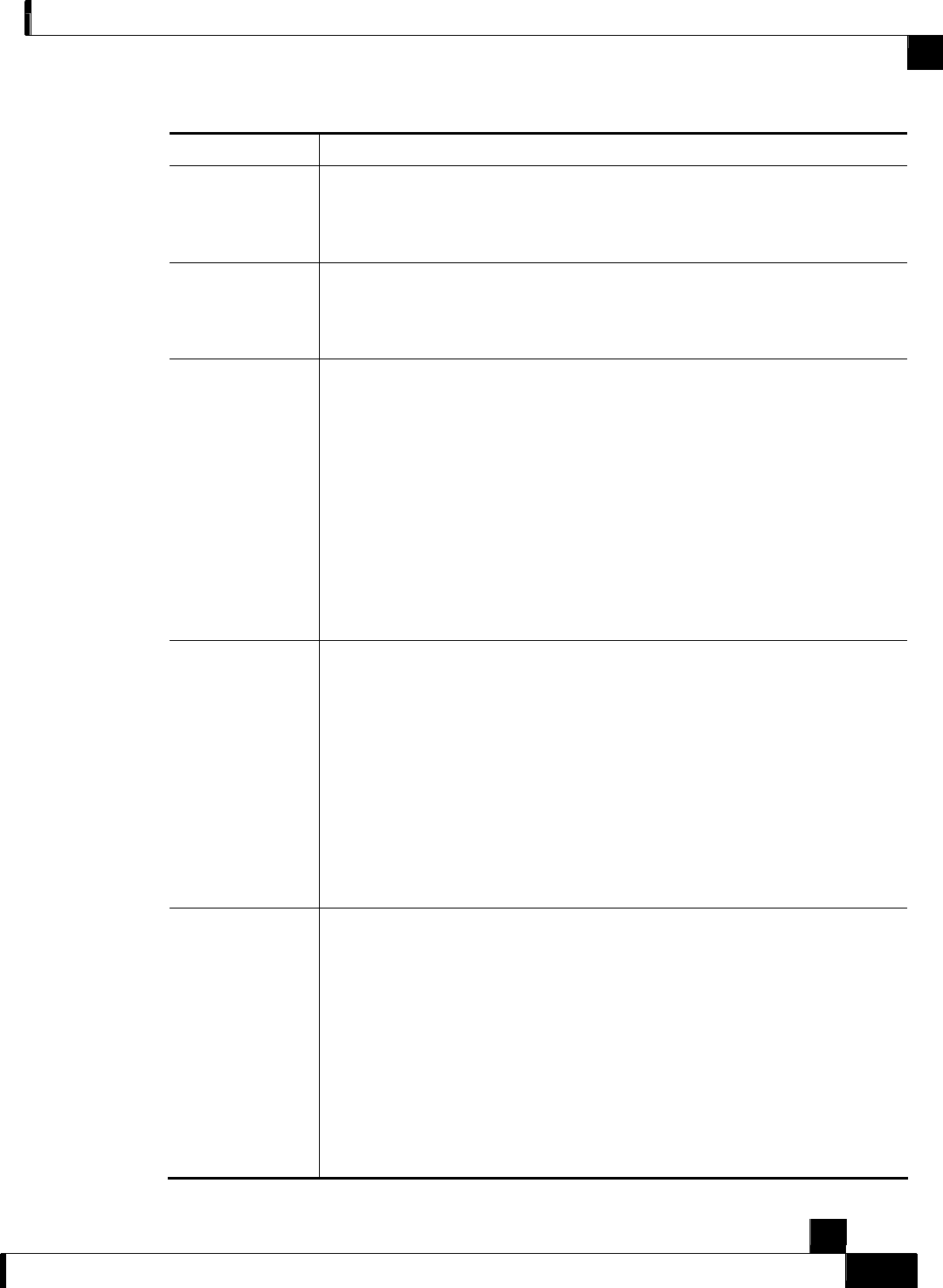
Table 2-3 SCE 2000 LED Groups
LED Groups Description
Power A
• Continuous green — Power supply A is functioning normally
• Red — Power supply A present, but malfunctioning
• Unlit — Power supply A is either not present or has failed.
Power B
• Continuous green — Power supply B is functioning normally
• Red — Power supply B present, but malfunctioning
• Unlit — Power supply B is either not present or has failed.
Status The Status LED indicates the operational status of the SCE 2000 system, as
follows:
• Unlit — indicates no power from either power unit.
• Orange — indicates that the system is booting up.
• Flashing green — indicates that the system is fully operational.
• Flashing orange — indicates that the system is operational, but is in a warning
state.
• Red — indicates that there is a problem or failure
Note that Alarms are hierarchical: Failure takes precedence over Warning, which
takes precedence over operational.
Bypass
• Continuous green — indicates that the traffic bypasses the SCE 2000 through
an internal electrical bypass module.
Single SCE 2000 topology — The SCE 2000 is either in bypass or sniffing
mode
Cascaded topology — Either the SCE 2000 is forwarding traffic to the other
SCE 2000, where it is being processed, or is simply in bypass mode, so traffic
through it is not being processed.
• Unlit — traffic is not being bypassed
Single SCE 2000 topology — indicates normal operation of the SCE 2000
Cascaded topology — indicates normal operation of the active SCE 2000
GBE ports The GBE LEDs indicate the operational status of the SCE 2000 line ports, as
follows:
• Link
Green — indicates that the port link is up
Unlit — indicates that the port link is down
• Rx
Flashing Green — indicates that there are incoming packets
• Tx
Flashing Green — indicates that there are outgoing packets