


Appendix A The External Optical Bypass Module
Installing the External Bypass Module
Cisco SCE 2000 4xGBE Installation and Configuration Guide
A-6 OL-7824-04
Warning
Auto-Negotiation should be configured identically for the two SCE 2000 platform GBE interfaces and
the GBE interfaces of the switch/router on either side of the External Optical Bypass module.
It is recommended that the two GBE interfaces of the SCE 2000 platform, as well as the GBE interfaces
of the switch/router on either side of the External Optical Bypass module, be configured to Auto-
Negotiation = OFF
Verify that the relevant GBE interfaces of the SCE 2000 platform are now in sync, as the External
Optical Bypass module is now active (in bypass), and is performing a loopback on these
interfaces.
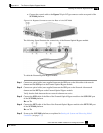
Step 6 Connect the control cable (supplied in the kit) from the Bypass 9-pin D-Type connector on the
rear panel of the SCE 2000 platform to the Control connector on the External Optical Bypass
module.
The SCE 2000 platform immediately starts providing power to the External Optical Bypass
module, so the bypass module becomes inactive, and starts transferring the traffic to the SCE
2000 platform. The “No Bypass” LED should therefore be lit.
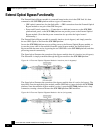
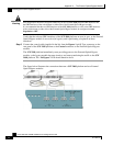
The figure below illustrates the connections between a SCE 2000 platform and two External
Optical Bypass modules.