


Chapter 6 Cabling the Line Ports and Completing the Installation
Connecting the line ports to the network
Cisco SCE 2000 4xGBE Installation and Configuration Guide
6-2 OL-7824-04
• Testing Connectivity: Examining Link LEDs, GBE Counters ("Testing Connectivity:
Examining Link LEDs and Counters" on page 6-9)
Cabling Diagrams
Before beginning, find the appropriate cabling diagram for the topology in your installation:
• Single SCE 2000 topologies
• Single Link: Inline Topology (on page 6-2)
• Single Link: Receive-only Topology (on page 6-3)
• Dual Link: Single SCE 2000 Topologies (on page 6-3)
• Dual SCE 2000 topologies (cascaded)
• Dual Link: Two SCE 2000s Topology (on page 6-5)
Note
When installing a cascaded system, it is extremely important to follow the sequence of procedures
outlined in the section Installing a Cascaded System (on page 6-10).
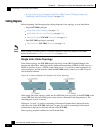
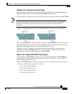
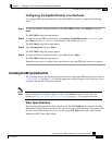
Single Link: Inline Topology
In the inline topology, the SCE 2000 resides physically on the GBE (Gigabit Ethernet) link
between the subscribers, which are usually connected through either a BRAS (in DSL access), a
PDSN (in wireless access), a CMTS (in the Cable access), or a switch or router aggregator (in
other topologies), and the network, where the SCE 2000 usually connects to a router or layer 3
switch network element.
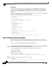
Figure 6-1: Cabling Diagram for Single Link Inline Topology
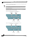
In the single link inline topology, either the first GBE link (first two ports) of the SCE 2000 or the
second GBE link (third and fourth ports) can be used, as illustrated in the diagram above. The
remaining pair of ports is unused.
Either port 1 or port 3 is used for connecting to the network element that is deployed on the
subscriber side of the SCE 2000 while port 2 or port 4 is used for connecting to the network
element that is deployed on the network side of the SCE 2000.
Inline topology requires both Receive and Transmit fibers