


Chapter 6 Cabling the Line Ports and Completing the Installation
Connecting the line ports to the network
Cisco SCE 2000 4xGBE Installation and Configuration Guide
6-8 OL-7824-04
Table 6-1 Fiber Specifications
SCE Model Transceiver Transmit Power Receive Power Typical (Max.) Distance
SCE 2000 4xGBE
MM
850nm Multimode –9.5 to –4 dBm –17 to 0 dBm
• 750m for 50µm Core
Diameter MMF
• 400m for 62.5µm Core
Diameter MMF
SCE 2000 4xGBE
SM
1310nm FRP laser
Single Mode
–9.5 to –3 dBm –20 to 3 dBm 10 km for 9.0µm Core
Diameter SMF
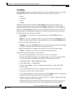
Cabling the GBE Port
Warning
Class 1 laser. Avoid exposure to radiation and do not stare into open aperture.
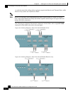
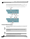
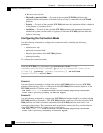
To cable the SCE 2000 GBE line port, complete the following steps:
Step 1 Take the appropriate fiber optic cable (see Fiber Specifications (on page 6-7)) and plug it into the
appropriate GBE port on the front panel of the SCE 2000.
Make sure to push on the connector until you hear a click, which indicates that the connector is
fully inserted and secured in the receptacle. Always make sure that you insert the connector
completely into the socket.
Figure 6-6: Cabling the GBE Interface
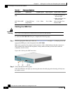
Step 2 Verify that the link LED is green.
If the link LED does not light, try removing the network cable plug and reinserting it firmly into
the module socket.