


If you manually configure the system priority, you must ensure that you assign the same priority value on
both vPC peer switches. If the vPC peer switches have different system priority values, the vPC will not
come up.
Note
Peer-Keepalive Link and Messages
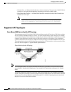
The Cisco NX-OS software uses a peer-keepalive link between the vPC peers to transmit periodic, configurable
keepalive messages. You must have Layer 3 connectivity between the peer switches to transmit these messages;
the system cannot bring up the vPC peer link unless a peer-keepalive link is already up and running.
If one of the vPC peer switches fails, the vPC peer switch on the other side of the vPC peer link senses the
failure when it does not receive any peer-keepalive messages. The default interval time for the vPC
peer-keepalive message is 1 second. You can configure the interval between 400 milliseconds and 10 seconds.
You can also configure a timeout value with a range of 3 to 20 seconds; the default timeout value is 5 seconds.
The peer-keepalive status is checked only when the peer-link goes down.
The vPC peer-keepalive can be carried either in the management or default VRF on the Cisco Nexus device.
When you configure the switches to use the management VRF, the source and destination for the keepalive
messages are the mgmt 0 interface IP addresses. When you configure the switches to use the default VRF, an
SVI must be created to act as the source and destination addresses for the vPC peer-keepalive messages.
Ensure that both the source and destination IP addresses used for the peer-keepalive messages are unique in
your network and these IP addresses are reachable from the VRF associated with the vPC peer-keepalive link.
We recommend that you configure the vPC peer-keepalive link on the Cisco Nexus device to run in the
management VRF using the mgmt 0 interfaces. If you configure the default VRF, ensure that the vPC
peer link is not used to carry the vPC peer-keepalive messages.
Note
Compatibility Parameters for vPC Peer Links
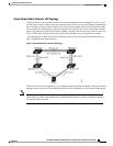
Many configuration and operational parameters must be identical on all interfaces in the vPC. After you enable
the vPC feature and configure the peer link on both vPC peer switches, Cisco Fabric Services (CFS) messages
provide a copy of the configuration on the local vPC peer switch configuration to the remote vPC peer switch.
The system then determines whether any of the crucial configuration parameters differ on the two switches.
Enter the show vpc consistency-parameters command to display the configured values on all interfaces in
the vPC. The displayed configurations are only those configurations that would limit the vPC peer link and
vPC from coming up.
The compatibility check process for vPCs differs from the compatibility check for regular EtherChannels.
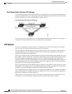
Configuration Parameters That Must Be Identical
The configuration parameters in this section must be configured identically on both switches at either end of
the vPC peer link.
Cisco Nexus 5000 Series NX-OS Interfaces Configuration Guide, Release 5.2(1)N1(1)
78-26881-OL 71
Configuring Virtual Port Channels
Peer-Keepalive Link and Messages