


iDP3310 User's Manual
8 CITIZEN
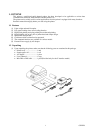
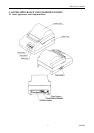
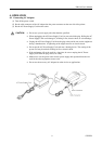
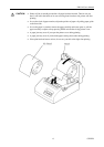
3.2 Description of Component Parts
(1) Printer cover
Open/close this cover when you replace the paper or correct its jamming.
(2) POWER lamp
This lamp is illuminated when the power is turned on.
(3) ERROR lamp
This lamp blinks when the paper runs out, and it is illuminated when the printer is mechanically locked.
(4) FEED switch
Press this switch when you want to feed the paper. The paper is fed while it is being pressed. Test printing
will be performed if you turn on the power while holding down this switch.
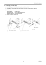
(5) Power connector
Connect an accessory AC adapter.
(6) Interface connector
Connect a connector cable meeting the specification.
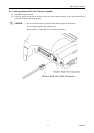
(7) Drawer kick-out connector(D type only)
Connect a drawer kick-out connector cable.
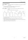
(8) DIP switches
These switch are to initially set communication, print density, and so on. (Located under the bottom of the
main body. See “5. DIP SWITCH SETTING .”)