


iDP3310 User's Manual
22 CITIZEN
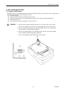
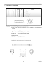
6.3 Input and Output Signals
6.3.1 Input and Output Signals
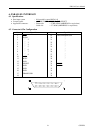
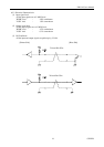
(1) Input Signals to the Printer
•
DATA : 8-bit parallel signal. (Positive logic)
•
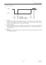
STB : Strobe signal to read 8-bit data. (Negative logic)
•
RESET : Signal to reset the entire printer (Negative logic) 1m sec more
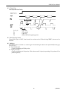
(2) Output Signals from Printer
•
ACK : An 8-bit data request signal. Pulse signal output at the end of the BUSY signal.(Negative
logic)
•
BUSY : The signal to indicate BUSY state of the printer. Input new data for "LOW."(Positive logic)
•
FAULT : The signal which is made "LOW" when the printer is in alarm state. All the control circuit
inside the printer are stopped at this time.(Negative logic)
•
SELECT : The signal which is made "HIGH" when the printer is ready to receive the data. (Positive
logic)
(3) Power related signal
•
GND : This is the common ground for the circuits.