


iDP3310 User's Manual
49 CITIZEN
ESC * m n1 n2 [d] k
ALL
[Function] Specify Bit Image Mode
[Code] <1B>H<2A>H<m><n1><n2>[<d>]k
[Range] m = 0, 1
0
≤
n1
≤
252
n2 = 0
0
≤
d
≤
255
k = n1 + 256
×
n2
[Outline] This command specifies the bit image of the m-mode as to the numbers of dots specified with
n1 and n2.
•
Divide the number of dots printed by 256 and assume a quotient to be n2 and a remainder
to be n1. Therefore, the number of horizontal dots will be n1 + 256 x n2.
•
If the bit image data is input beyond the number of dots printable in one line, the surplus
data will be discarded.
•
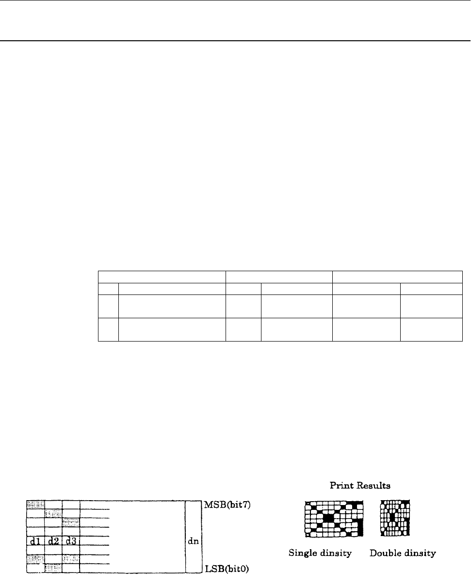
d denotes the bit image data. Set “1” in the corresponding bit to print, and “0” not to print.
•
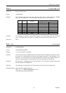
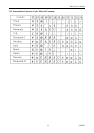
The following table lists the bit image modes selected by m.
Vertical Direction Horizontal Direction
m Mode Dots Dot Density Dot Density Max. Dots
0 8-dot single density 8 77DPI 50DPI
120
126
1 8-dot double density 8 77DPI
101DPI
240
252
♦
The upper figure in the Max. Dots column is for the P-200 mode or 40-column mode, and
the lower figure is for the P250 mode, P-900R mode, or 42-column mode, respectively.
[Caution] If the m-value is beyond the limits, the data after n1 will be processed as normal data. Normal
data processing is restored after printing the bit image.
[Sample Program] LPRINT CHR$(&H1B)+"
*
"+CHR$(0)+CHR$(10)+CHR$(0);
LPRINT CHR$(&H81)+CHR$(H42)+CHR$(&H24)+CHR$(&H18);
LPRINT CHR$(&H18)+CHR$(&H24)+CHR$(&H42)+CHR$(&H81);
LPRINT CHR$(&HC8)+CHR$(&H8F);