


Crestron TPS-GA-TPI Isys
®
G-Series Touchpanel Interface
Operations Guide – DOC. 6501 Isys
®
G-Series Touchpanel Interface: TPS-GA-TPI • 7
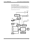
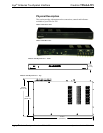
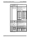
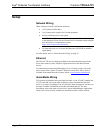
TPS-GA-TPI Physical View – Rear
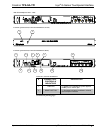
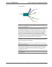
Location of Connections, Controls and Indicators (Front)
1 2
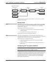
Location of Connections, Controls and Indicators (Rear)
3
4
5
6
7
8
9
10 12
13
14
11
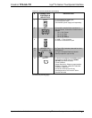
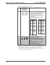
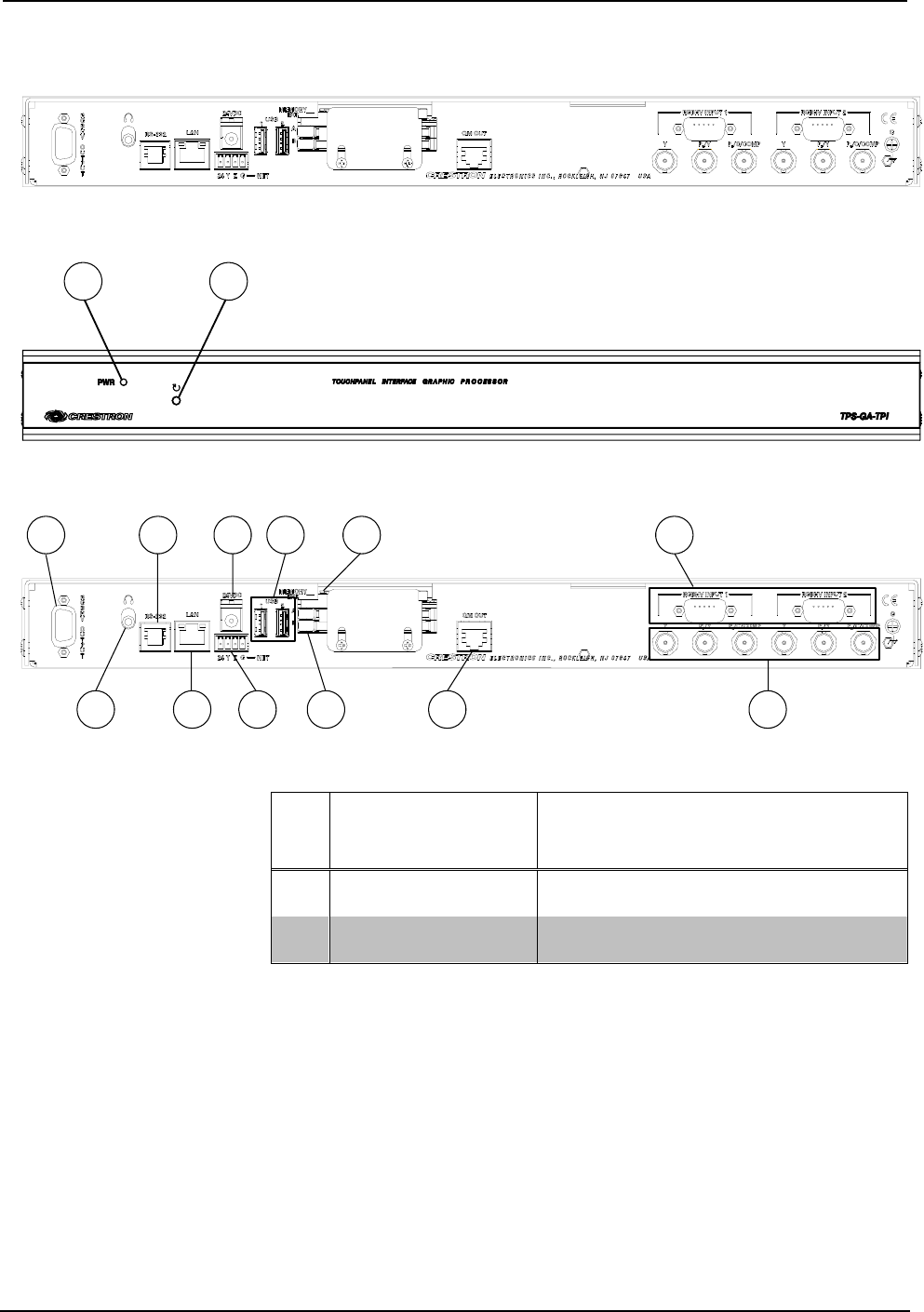
Connectors, Controls & Indicators
#
CONNECTORS
1
,
CONTROLS &
INDICATORS
DESCRIPTION
1 PWR LED
(1) Green LED, indicates DC power applied
to NET port or 24VDC jack.
2 RESET BUTTON
(1) Recessed miniature pushbutton, reboots
the touchpanel interface.
(Continued on following page)