


Isys
®
G-Series Touchpanel Interface Crestron TPS-GA-TPI
10 • Isys
®
G-Series Touchpanel Interface: TPS-GA-TPI Operations Guide – DOC. 6501
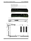
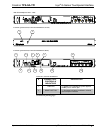
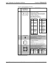
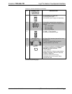
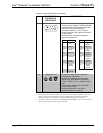
Connectors, Controls & Indicators (Continued)
#
CONNECTORS
1
,
CONTROLS &
INDICATORS
DESCRIPTION
13
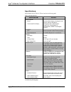
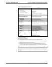
RGBHV IN (1 – 2)
(2) DB15HD female, RGB (VGA) inputs;
Analog Formats: RGBHV, RGBS and RG
S
B
Input Resolution, Non-interlaced: 640x480
minimum to 1600x1200 maximum;
Horizontal Frequency: 31.5 to 100 kHz
Vertical Frequency: 60 to 85 Hz (60 Hz limit
at 1600x1200)
Standard HD15 connector configured to
optimize performance.
2
PIN SIGNAL
PIN SIGNAL
1 Red 9 No
Connect
2 Green 10 Ground
3 Blue 11 No
Connect
4 Reserved 12 Monitor
Sense
5 Ground 13 Horizontal
Synch
6 Red
Ground
14 Vertical
Synch
7 Green
Ground
15 Monitor
Sense
Clock
8 Blue
Ground
14 VIDEO IN (1 – 2)
(2) sets of (3) BNC female connectors
comprises (2) video inputs,
Dynamically configurable under system
control as (1) auto-detecting component
(YP
b
P
r
), S-Video (Y/C), or composite video
input
Formats: 480i (NTSC), 576i (PAL), 480p,
576p, 720p and 1080i;
Horizontal Frequency: 15 to 45 kHz
Vertical Frequency: 50 to 60 Hz
1. Interface connectors for NET port is provided with the unit.
2. Refer to the Crestron website or contact Crestron for the latest firmware capabilities and device
support. Connect to external touchscreen via part number 4501251 (supplied) or CNPS-602,
CNSP-616, CNSP-617, CNSP-621 or CNSP-622 (available separately—call Crestron).
3. The TPS-GA-TPI can be powered via the 24 VDC jack OR the NET port. Be sure to use a Crestron
approved power supply as another may cause damage.