


Crestron TPS-GA-TPI Isys
®
G-Series Touchpanel Interface
Operations Guide – DOC. 6501 Isys
®
G-Series Touchpanel Interface: TPS-GA-TPI • 3
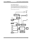
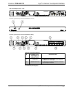
Internal Block Diagram
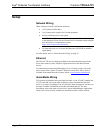
The following diagram represents the internal configuration of the TPS-GA-TPI.
These units feature two RGBHV inputs to receive RGBS and RGsB from a computer
and two sets of three BNC connectors to receive video and HDTV (composite,
S-video, and component) inputs. There is also a QM output for connection to a QM
receiver or switcher. For more information, refer to “QuickMedia Wiring” on page
12.
Internal Block Diagram of the TPS-GA-TPI
Controller/CPU
Mixer DSP
QM
Out
Memory Expansion
USB Ports (2)
Cresnet
Ethernet
RS-232
AMP
Video Digitizer
Graphics Processor
Headphone
Jack
RGBHV
OUT
SW1
(RESET)
WAV
PLayer
RGBHV
IN 2
RGBHV
IN 1