


Crestron TPS-GA-TPI Isys
®
G-Series Touchpanel Interface
Operations Guide – DOC. 6501 Isys
®
G-Series Touchpanel Interface: TPS-GA-TPI • 41
Uploading and Upgrading
Crestron recommends using the latest programming software and that each device
contains the latest firmware to take advantage of the most recently released features.
However, before attempting to upload or upgrade it is necessary to establish
communication. Once communication has been established, files (for example,
programs, projects or firmware) can be transferred to the control system (and/or
device). Finally, program checks can be performed (such as changing the device ID
or creating an IP table) to ensure proper functioning.
Establishing Communication
Use Crestron Toolbox for communicating with the TPS-GA-TPI; refer to the
Crestron Toolbox help file for details. There are three methods of communication.
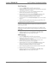
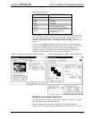
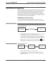
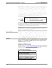
Direct Serial Communication
NOTE: Required for initial setup of Ethernet parameters.
Direct Serial Communication
PC RUNNING
SERIAL VIA CRESTRON
CABLE STCP-502PC
OR EQUIVALENT
CRESTRON TOOLBOX
TPS-GA-TPI
• The RS-232 port on the TPS-GA-TPI connects to the serial port on the PC
via a serial cable (Crestron STCP-502PC or equivalent).
• Use the Address Book in Crestron Toolbox to create an entry using the
expected serial communication protocol (RS-232, auto-detect baud rate, no
parity, 8 data bits, 1 stop bit, XON/XOFF disabled, RTS/CTS disabled).
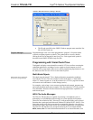
• Display the TPS-GA-TPI’s “System Info” window (click the
icon);
communications are confirmed when the device information is displayed.
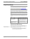
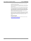
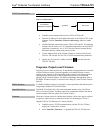
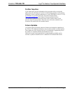
Indirect Serial Communication
Indirect Serial Communication
PC RUNNING
CRESTRON TOOLBOX
CONTROL SYSTEM TPS-GA-TPI
SERIAL,
ETHERNET
OR USB
CRESNET
• TPS-GA-TPI connects to control system via Cresnet.
• Establish communications between the PC and the control system as
described in the latest version of the 2-Series Control Systems Reference
Guide (Doc. 6256).